www.Wayne-Dalton.com
349981 REV2_05/17/2016
©
Copyright 2016 Wayne Dalton, a division of Overhead Door Corporation
55
rubber band seal
phillips head screw
dust cover
shaft seal
spacers
and gap
adjustment
shims
gap adjustment
shims
mechanical
brake
release handle
Hex head
screw
Stopper
Brake Gap Inspection and Adjustment
1.
Fully
close door
,
remove power
.
•
Use proper lock out/tag out procedures.
2.
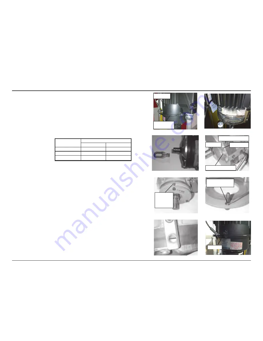
Remove Winding Eye cover,
Fig. 8–C.
A.
Remove E-clip from the mechanical brake release handle.
B.
Remove mechanical brake release handle.
C.
Pull the mechanical release lever out of the brake assembly.
D.
Remove three screws from the Winding Eye Cover and slide the Cover off.
3.
Pull the rubber band seal down and insert a gap gage between the Stationary Core and
Armature plate to measure the gap,
Fig. 8–D.
•
Adjustment is needed if the gap is close to the allowable limit shown on the Gap
Chart below.
– Gap measurements should be taken at 3 points, 120° apart.
Motor HP
Gap Value
Specification
Allowable Limit
1/2 HP
0.006 - 0.010
0.020
1 HP
0.008 - 0.012
0.020
1 HP
0.008 - 0.012
0.020
Gap Chart
– If the measured gap is within specifications, replace the Winding Eye cover, hex head
screws, mechanical brake release handle and E-clips.
4.
When the measured gap is out of specification:
A.
Remove screw and nut from Winding Eye and remove Winding Eye"
Fig. 8–E.
B.
Remove Allen screws and mechanical release supports.
C.
Remove three Phillips head screws and dust cover including the rubber shaft seal,
Fig. 8–F.
D.
Remove the rubber band seal.
FOR 1/2 HP MOTOR ONLY;
Loosen restraining bolt, rotate brake shoe one complete turn
counterclockwise and retighten restraining bolt.
Re-measure gap.
E.
Slowly loosen the Allen retaining screws on the brake shoe. Alternate between screws
so that spring pressure is released evenly.
– When spring pressure is released, carefully remove the retaining screws, making sure
to keep the spacers and gap adjusting sleeves,
Fig. 8–G.
F.
Remove spacers from the retaining screws and remove gap adjusting shims necessary
to achieve proper gap,
Fig. 8–H.
5.
Reassembly is the reverse of disassembly.
NOTE:
When replacing the rubber band seal, be careful to line up the holes in the seal with
the holes in the mechanical release supports. Alignment must be "dead on" or the mechanical
release levers will not properly reinstall,
Fig. 8–I.
NOTE:
When replacing the manual operation yoke, line up the pin with the hole through the
motor shaft and press into place.
NOTE:
When finished with reassembly double check to ensure the mechanical release handle
is resting on the bottom of the stopper.
Fig. 8-J
Fig 8–I
Fig 8–G
Fig 8–H
Fig 8–E
Fig 8–F
Fig 8–C
Fig 8–D
Fig 8–J


