background image

www.Wayne-Dalton.com

349981     REV2_05/17/2016

©

Copyright 2016 Wayne Dalton, a division of Overhead Door Corporation

38

MENUS 

(continued)

3. Profile Selection Menu

The profile selection is done at the factory by default. Profiles can be selected based on the door the 

controller is operating. The profile is protected by a passcode, and can only be changed by Overhead service representative. All 

settings are lost and reverted back to defaults when the profile is changed. Profiles can be accessed through the main menu under Profile

Selection.


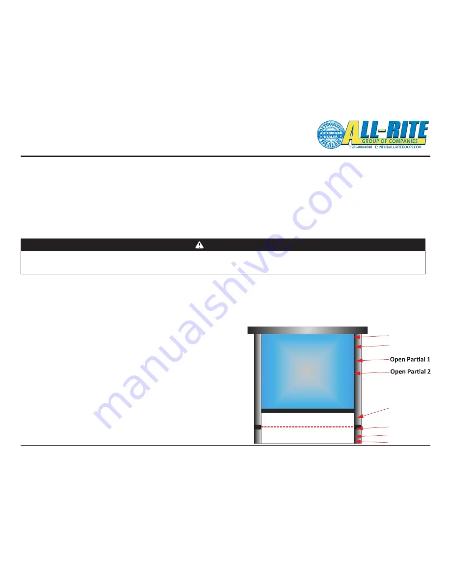
4. Limit Setup Menu

Individual limits can be updated manually, however; the best option is to use the quick setup process as discussed earlier. The door will not be 

operational when settings limits. Limit settings are as described: 

To configure the Limit Settings manually after using Quick Setup, select each

individual position listed below from the Limit Setup menu, then move the door to the

desired position. Store the position by pressing STOP or ENTER

when finished. The display shows Stored and returns to the previous menu.

• Closed: Door fully closed.

• Pre Closed: Position where door changes to pre-closing speed during close.

• Pre Open: Position where door changes to pre-open speed during open.

• Open: Door fully closed.

• Open Part 1: Partially open position 1. Door opens to this position when a part 1

open input is active. (default: 75% of door open limit)

• Open Part 2: Partially open position 2. Door opens to this position when a part 2

Fully Open

Pre-Open

Fully Closed

Rev Edge OFF

Photocell OFF

Pre-Closed

open input is active. (default: 50% of door open limit)

• Rev. Edge OFF: Sets door position where safety edge check is turned off: the limit

where the reversing safety edge should be ignored.

• Photocell Off: Sets door position where photocell should be ignored.

Fig 6–B

WARNING

All Entrapment Protection Devices are 

OFF

 when setting limits.  Devices 

OFF 

while setting Limits include: Edge Contact, Photoeye, Wall push buttons, 

Radio Control, Limit Sensors, Loop Detector, or any motion sensor used as either an actuator or an Entrapment Protection Device.  Only the Interlock 

remains active.

USE CAUTION!  Do NOT use for general door operation when setting limits.

Содержание 800

Страница 1: ...This installation manual provides the trained door technician information required to install troubleshoot and maintain a Wayne Dalton Advanced Performance Option Service Door READ COMPLETE INSTRUCTIONS BEFORE INSTALLING DOORS Installation repairs and adjustments must be made by a trained door system technician using proper tools and instructions INSTALLER Leave this manual with the end user Pleas...

Страница 2: ...1 Section 5 22 31 Wiring 22 240V Motor Wiring 23 480V Motor Wiring 23 Main Component Overview 24 Control Panel Contents 25 Control Panel Wiring Diagram 26 Control Panel Cables 27 Junction Box Wiring 28 Section 5 continued Photoeye Adjustment 29 Control Wiring Low Voltage 29 Position Sensor Wiring Connections Settings 30 Accessory Wiring Diagrams 31 Reference Conventional Wire Routing 32 Wiring Che...

Страница 3: ...voided may result in injury or property damage The word NOTE is used to indicate important steps to be followed or important considerations 1 Read manual and warnings carefully 2 Keep the door in good working condition 3 This door is equipped with a sensing edge check sensing edge operations daily Make any necessary repairs to keep it functional 4 All models are equipped with an overcurrent device...

Страница 4: ...voltage supply e g 208 Y 120 480 Y 277 Ungrounded voltage supply sources must be avoided e g 480 VAC 240 VAC or 120 VAC Delta systems should NOT be used Voltage unbalance is a common occurrence on Delta supply systems which power both single phase and three phase loads which can lead to unequal voltages on each phase leg Voltage unbalance can cause deterioration of motor performance such as loss o...

Страница 5: ...Manual Provides an overview of component information and how to use this manual Section 3 General Information Details pre installation issues that are recommended to be considered and or resolved prior to beginning this door system installation Section 4 Installation Provides step by step physical installation instructions for this product Section 5 Wiring Provides step by step wiring instructions...

Страница 6: ...hown Door Opening Interior Hood Drive End Hood Rotary Transducer Junction Box Hand Crank Interlock Switch Motor Ballast Resistor Brake Release Cord Motor Brake Release Pull Cord Warning Tag Control Panel Keypad Coil Cable Safety Label With Instructions Hand Crank Sensing Edge Photo Cell Transmitter Cover Plate Assembly NOTE That Photo Cell location s may be different for your unit Guide Opening Le...

Страница 7: ...op detectors photoeyes key switches motion detectors etc Accessory equipment needs and requirements Examples include sirens warning lights etc Job Site Issues Considerations Door Specifications DOOR MODEL NUMBER circle one 800 800C OPENING WIDTH OPENING HEIGHT CURTAIN COLOR OPERATOR VOLTAGE HEADROOM REQUIREMENT CURTAIN WEIGHT __________ SIDE ROOM DRIVE__________ NON DRIVE __________ GUIDE GAP ____...

Страница 8: ...T Ensure the door installation can be accomplished before proceeding Check that the wall opening Fig 3 B matches the Opening Width and Height shown on the Installation Data Sheet Check that the sill is level and plumb Verify the guides you received are suitable for the jambs Compare the guide type on the Installation Data Sheet with Fig 3 C V V Fig 3 A Fig 3 B Wall Angle Z Guide Outside Angle E Gu...

Страница 9: ...welded or screwed use E guides all others use Z SCREW ATTACHMENT OPTION Hold E Guide wall angle against the jamb and drill holes through the slots using drill size shown in Table 4 A Install all jamb fasteners Table 4 A on one wall angle then install second wall angle at G S 1 2 Fig 3 C distance Check for level and plumb WELD ATTACHMENT OPTION Hold E Guide wall angle against the jamb and tack weld...

Страница 10: ...barrel assembly Fig 4 E DO NOT tighten set screw at this time B Slide spacer collar onto the drive end shaft of the barrel assembly The spacer collar separates the set collar from the headplate bearing and has no set screws C Slide set collar 1 1 2 ID with set screw onto non drive end shaft of the barrel assembly DO NOT tighten set screw at this time D Slide spacer collar onto the non drive end sh...

Страница 11: ... provided to inside of gearmotor bearing A Slide the drive headplate bracket bearing and gearmotor drive bracket onto drive end of the barrel shaft long end B Align keyways and insert supplied key If possible leave key flush with the shaft end It can be used to align drive sprocket Do not trim yet C Slide the non drive headplate bracket and bearing onto the non drive end of the barrel shaft short ...

Страница 12: ...e power be restored while the Hand Crank is engaged Do NOT disconnect power interlock switch TO OPERATE This task requires two 2 people to perform Installation of the Hand Crank and Interlock Switch occurs in Step 13A on page 16 A Disconnect ALL electrical power supply B Remove hand crank from the Crank Handle Support Bracket This releases the power interlock switch a backup protection to ensure t...

Страница 13: ...e doors attach the top slat to two slings ropes and rotate the slings ropes to bring the top slat into position If the barrel has rings Pull the curtain up and hold top slat against the rings Fig 4 K a Align the slots in the top slat with the holes in the rings Fasten the curtain to the rings with 3 8 16 x 5 8 Torx head screw and washers provided NOTE TAKE CARE TO PREVENT STRIPPING SCREW THREADS I...

Страница 14: ... Crank see page 12 prior to performing the following installation steps 12 OVERTRAVEL PREPARATION A Place locking pliers or other secure clamping tool on both guides at 2 to 3 inches below the channels on the guide angles as shown in Fig 4 N The guides are made up of the middle and outer angles The pair are referred to as the Guide Angles B Create slack in the slings ropes then using the hand cran...

Страница 15: ...be directly in line with each other to prevent sprocket wear and Position Sensor damage B Install Gear Motor Drive sprocket onto the door shaft Ensure the drive sprocket is aligned with the Position Sensor sprocket Use the supplied 1 4 X 1 4 key to lock it into the motor FIG 4 Q C Do NOT install Position Sensor chain at this time Chain will be installed during door set up after the control system ...

Страница 16: ...racket Interlock Switch and Hand Crank components that are near the motor and does NOT interfere with the operation or installation of other components Fig 4 R 2 Using appropriate fasteners and pre drilled holes mount the Crank Support Bracket to the wall 3 Using appropriate fasteners mount the Interlock Switch to the Crank Support Bracket 4 Place the hook end of the Hand Crank onto the Support Br...

Страница 17: ...m heat sources With no interference of moving parts of the door system Where cables can be well secured while preventing unnecessary strain Mount the Control Panel to the wall Fasteners not provided Use supplied mounting tabs as necessary Fig 4 S c D Photoeye assemblies are factory mounted to their protective shields Attach to guides as follows Fig 4 S c 1 Mount the Photoeye Receiver pre wired cab...

Страница 18: ...e supplied bracket and accessible guide assembly bolt at approx 2 3 of door opening height Fig 4 T b 3 Route coil cord to conduit box mounted on guide rail Ensure that coil cord remains free from tangling on other components or fixtures 4 Connect the coil cord wire to the supplied 3 wire M12 cable inside the conduit box Use only the Black and White wires cut off the Red wire 5 Route the supplied M...

Страница 19: ...ROM DISCONNECT Fig 4 U 16 MOTOR POWER WIRING HIGH VOLTAGE These tasks are also diagrammed in Fig 5 D 5 G 5 H on pages 24 26 A Route Motor Power Cable provided factory wired to motor through water tight fitting in the SECOND hole from left side of Control Panel bottom 1 Connect the lighter gauge twisted pair wires to the blue colored Motor Brake terminals next to the disconnect switch Either wire c...

Страница 20: ...is not binding against the back of the guides If curtain is level at bottom but not at top place shims between the curtain and barrel on the low side E Verify good mechanical connection and tightness of fasteners i e guides headplates set screws F Position the door at the half open position NOTE Hood and Brush Seal installation can be delayed until the last step to allow easy access to curtain dur...

Страница 21: ... Is the door level square and plumb Are all the bolts tightened Are limit switch sprockets properly aligned Is the Drop Stop Device installed with the correct rotation ARE ALL BEARING AND SET COLLARS POSITIONED ARE SET COLLARS AND BEARING SET SCREWS TIGHTENED Has all the rigging equipment ropes straps locking pliers etc been removed Are all safety labels and tags in place Are all cable connections...

Страница 22: ... must be avoided e g 480 VAC 240 VAC or 120 VAC Delta systems should NOT be used Voltage unbalance is a common occurrence on delta supply systems which power both single and 3 phase load This can lead to unequal voltages on each phase leg Voltage unbalance can cause deterioration of motor performance such as loss of torque overheating decrease the winding insulation life and can cause motor starte...

Страница 23: ...R BRAKE 2 2 FACTORY WIRED these steps and illustration are for reference only NOTES 1 Slide the three black motor wires through the LARGE suppression core 800358 0002 2 Slide each black motor wire individually through one SMALL EMI suppression core 800358 0001 3 Make wiring connections as shown 480V Motor Wiring FACTORY WIRED these steps and illustration are for reference only NOTES 1 Slide the th...

Страница 24: ...rporation 24 Wiring Overview HANDLE DISCONNECT MOTOR CONTROLS LCD SCREEN 1 MAIN COMPONENT OVERVIEW Fig 5 C AND 5 D Fig 5 D Control Panel Bottom Wiring Access Fig 5 C Control Panel Front Cover MOTOR CABLE 5 PIN POSITION SENSOR CABLE 12 PIN JUNCTION BOX CABLE MAIN POWER FROM DISCONNECT 1 800 827 3667 DOOR ...

Страница 25: ...www Wayne Dalton com 349981 REV2_05 17 2016 Copyright 2016 Wayne Dalton a division of Overhead Door Corporation 25 Wiring Overview continued Fig 5 G Control Panel Contents See also FIG 8 H ...

Страница 26: ... 2016 Copyright 2016 Wayne Dalton a division of Overhead Door Corporation 26 Wiring Overview continued Fig 5 H Control Panel Wiring Diagram 480V GND BOX MOTOR FROM DISCONNECT MAIN POWER POSITION SENSOR JUNCTION MEMBRANE BUTTONS FRONT COVER ...

Страница 27: ...4 TO JUNCTION BOX SENSING EDGE WHITE 1 INTERLOCK GREEN 2 NOT USED 3 PHOTOEYE RECEIVER GRAY 4 OPTION 1 PINK 5 OPTION 2 RED 6 NOT USED 7 NOT USED 8 NOT USED 9 10 COMMON 0V BLUE 11 POWER 24V BROWN 12 GND GREEN YELLOW BOTTOM OF CONTROL PANEL TO POSITION SENSOR 12V BROWN 1 A SIGNAL WHITE 2 B SIGNAL BLUE 3 OV BLACK 4 PULSE GRAY 5 FROM JUNCTION BOX POSITION SENSOR CABLE 10 12 1 2 3 4 5 6 7 8 9 11 KEY 5 K...

Страница 28: ...nnections for most factory wired external control functions Wiring Overview continued CAUTION Ensure all openings into junction box are weather tight to prevent leakage TO LOOP DETECTOR OR MOTION DETECTOR BLACK TO RADIO REMOTE RECIEVER BLACK TO PHOTOEYE TRANSMITER GREEN TO PHOTOEYE RECIEVER CYAN TO SENSING EDGE RED TO HAND CRANK INTERLOCK ORANGE ...

Страница 29: ...the Photoeyes out of alignment PHOTOEYE TRANSMITTER PHOTOEYE RECEIVER Photoeye cables are wired at the factory with a M12 connector wire colors are for reference NO FIELD WIRING REQUIRED GND GND 24V 24V SIGNAL WHITE BOX INDICATES SETTING TIMER TURNED CCW ALL THE WAY Fig 5 K Fig 5 L Fig 5 M PHOTOEYE Photoeyes are attached to their protective shields at the factory and must be mounted to the guides ...

Страница 30: ...Step 13 See page 15 A Attach the chain to the Motor and Position Sensor sprockets Adjustment of the supplied chain may be necessary FIG 5Oa B Attach one end of the M12 position sensor cable to the Position Sensor C Attach the other end of the M12 position sensor cable to the Control Panel Fig 5 Ob Position sensor Cable FEMALE END VIEW TO CONTROL PANEL SHIELD 4 1 2 3 5 SHIELD 4 3 2 1 5 MALE END VIE...

Страница 31: ... 5 Options wiring and settings Wire the supplied cables to the following options as shown in FIG 5 OC FIG 5 OD FIG 5 OE A For the radio receiver wire the supplied receiver load into the control unit from MAN1 to 24VDC blue terminal CAUTION Door will open close once connected 1 Access the menu and navigate to system config Inputs Man1 Logic 2 Select NC parameter and exit the menu B The motion detec...

Страница 32: ...ed in this section check Wiring Check List WARNING Making the checks outlined below will help to ensure that the unit is wired properly CHECK Double check all connections are tight Check all cables are secured not hanging loose where they might become interference Ensure there are no loose tools or materials inside the Control Panel or Junction Box Wiring continued OPTION 1 OPTION 2 MAIN POWER JCT...

Страница 33: ...oubleshooting Section 8 B Verify the RED LED is steady ON on the Photoeye Receiver If the RED LED is NOT ON loosen the mounting screws and adjust the Photoeye positions until the RED LED is steady ON Tighten the mounting screws If the RED LED does NOT come ON review the Photoeye installation steps on page 17 Refer also to Troubleshooting Section 8 WARNING All Entrapment Protection Devices are OFF ...

Страница 34: ...ter into Quick Setup A code request screen will appear Enter the 3 digit passcode to gain access by scrolling up or down Your passcode is located on a seperate addendum NOTE Do not display or freely give out the passcode 4 Follow the prompts in order to set the open and close limits on the door During this time use the OPEN CLOSE buttons to move the door Again the STOP button will be used as the E...

Страница 35: ...ne Dalton com 349981 REV2_05 17 2016 Copyright 2016 Wayne Dalton a division of Overhead Door Corporation 35 Fig 6 A Note Not all Menus are accessible Passcodes are required to access higher systems operations ...

Страница 36: ...menu option C Enter to view the highlighted option D Press and hold STOP or ENTER when finished to return to the System Status menu E Repeat to view other parameters if desired Overview displays status and current position of Photocell and Safety Edge reversing edge 1 To view status and current position of photocell 2 Safety Edge 2 scroll up Position shows the internal door position count The batt...

Страница 37: ...g cycles the door has completed open close 1 cycle Note This is already shown by default at the top left corner in the main screen Temperature shows the internal temperature of the DGII Controller This is a raw analog value and does not represent degrees centigrade or Fahrenheit A display on the bottom graphically approximates either a Low or High tem perature DC Link shows the internal DC Link vo...

Страница 38: ...ER when finished The display shows Stored and returns to the previous menu Closed Door fully closed Pre Closed Position where door changes to pre closing speed during close Pre Open Position where door changes to pre open speed during open Open Door fully closed Open Part 1 Partially open position 1 Door opens to this position when a part 1 open input is active default 75 of door open limit Open P...

Страница 39: ...ot update menu is not used H Motor Configuration Do not update Engineering use only I Frequencies Do not update Tech Services use only J Ramps Do not update Tech Services use only K DG XNET Do not update Menu not used L Options Do not update Menu not used M System Do not update Engineering use only 6 Configuration Inputs Outputs A Inputs There are 3 parameters that can be set Refer to FIG 6 C clos...

Страница 40: ...ng this input unlocks the door and allows normal operation Lock Close Activation causes the controller to hold the door at the fully closed position limit The input must be continously activated to maintain the locked open state Deactivating this input unlocks the door and allows normal operation Open Jog Activation of this input moves the door in the direction of the fully open limit at Jog speed...

Страница 41: ...or is moving in the close direction Delay to Close Output is active when the Delay To Close timer is greater than zero and the door is commanded to close The output remains active for the duration of the Delay To Close timer Delay to Open Output is active when the Delay To Open timer is greater than zero and the door is commanded to open The Open button must remain active until the Delay To Open t...

Страница 42: ...The items in the Fault Log are listed in reverse chronological order with number 1 being the most recent and the highest number being the oldest If NO keys are pressed for 120 seconds display will exit back to the main menu Motion can occur and panel responds normally to inputs while in the System Status Menus Set Up Check List CAUTION Check ALL items below to ensure that the Control Panel is inst...

Страница 43: ...www Wayne Dalton com 349981 REV2_05 17 2016 Copyright 2016 Wayne Dalton a division of Overhead Door Corporation 43 Section 7 Troubleshooting DROP STOP DEVICE ...

Страница 44: ...r to confirm Drop Stop Device activation Test 1 A Note and clear error messages from Control Panel Do NOT press OPEN key B Press CLOSE key If door does NOT close Drop Stop Device has been activated Contact service representative If door closes Drop Stop Device has NOT been activated Refer to error messages originally displayed Contact a service representative to take corrective action C Press OPEN...

Страница 45: ...s critical to the functionality of the Drop Stop Device DSD and is adjustable The spring tension must be adjusted tight enough such that normal operation of the door with or without a motor operator will not engage the pawl into the stator ring yet loose enough so that rapid rotation will engage the pawl Component Identification STANDOFF STATOR RING ROTOR HUB NON DRIVE END HEADPLATE PAWL STATOR RI...

Страница 46: ...h the STOP button in the event that the Pawl engages the stator Pawl reset Procedures NOTE The latch will prevent the pawl from back rolling if the door bounces when engaging as shown in Fig 7 B To disengage the Pawl the operation will need two 2 persons one to unlock the latch and another to press OPEN button on the control panel to disengage the Pawl To unlock the Latch press the bottom of the L...

Страница 47: ...position shown in Fig 7 E Six standard steel 3 4 bolt washers 13 16 ID X 2 OD X 145 thick will make about 10 ounces E The 10 ounce weight should rotate the pawl to the position shown in Fig 7 F Adjust If the pawl is higher than this position spring tension is too high Move the spring clip to loosen the spring until the pawl does lower to align as shown in Fig 7 F If however the pawl bottoms on the...

Страница 48: ...onnector UP Button DOWN Button Wiring Guide Reversing Edge Terminal Block Safety Terminal Block Photocell Connections Control Output Power Terminal Block Motor Connection Braking Resistor Connection some models Output Relay Terminal Block ConfigurableInputs Terminal Block RS 485 COM Terminal Block Motor Encoder Connection Input Power Connections Mains Brake Connection optional Menu Enter Button Fig...

Страница 49: ...mon should be set to 24V Stop is set to NC in firmware System config Inputs Open is set to NO Close is set to NO Refer to Fig 7 J page 50 General service Due XXXXX Routine service interval has elapsed Contact distributor for required maintenance Major service Req d XXXXX Required maintenance interval has elapsed Contact distributor for required maintenance Door stops for no reason or acts differen...

Страница 50: ...ive STATUS Idle Door at rest not at open close mid limits Displayed when door is motionless in Idle and not at open close open P1 limits Door stopped using the STOP key STATUS Count down Door at rest and counting down to timed close or open Time remaining in seconds is displayed STATUS OPENING Opening Door opening Displayed while door is opening from activation STATUS CLOSING Closing Door closing ...

Страница 51: ...or mechanical obstruction or damage INV_ERROR_OC3 Overcurrent during acceleration Overcurrent while accelerating View the Motor Current display to see the current delivered to the motor Decrease the acceleration ramps INV_ERROR_OC4 Overcurrent DC Brake Medium Priority Overcurrent while DC braking View the Motor Current display to see the current delivered to the motor Decrease the DC Brake level I...

Страница 52: ...nsure a correct value E08 Safety Edge Test Fail Medium Priority The Reversing Edge test has failed Check the connections from the reversing edge to the controller If using the Seywave wireless system check operation of connected host and remote door sensor E09 Safety Edge Connection Medium Priority The Reversing Edge connection cannot be verified Check the connections from the reversing edge to th...

Страница 53: ...ensor remote has reported a connection fault Check the connection and remote for operation Refer to supplied Seywave Wireless manual for troubleshooting E24 N A E25 Manual Crank input active Medium Priority Manual Crank is off the Support Bracket Put Hand Crank back on the Support Bracket E26 Overtravel error HIGH PRIORITY Door moves beyond limits Reset limits E27 Photoeye connection test fail Med...

Страница 54: ... service is completed clear the service message by going into System Configuration System Clear counter Table 8 A General Inspection Visually inspect wiring conduit and cables Inspect fixtures such as Bearings conduit boxes hood gear box for oil leakage motor Inspect safety labels placement and condition Lubricate guides with paste wax or silicone spray Position Sensor Chain Tension and Alignment ...

Страница 55: ...n the measured gap is out of specification A Remove screw and nut from Winding Eye and remove Winding Eye Fig 8 E B Remove Allen screws and mechanical release supports C Remove three Phillips head screws and dust cover including the rubber shaft seal Fig 8 F D Remove the rubber band seal FOR 1 2 HP MOTOR ONLY Loosen restraining bolt rotate brake shoe one complete turn counterclockwise and retighte...

Страница 56: ...s Breakdown Parts Drawing Section 9 NOTE Fasteners and some parts not shown for clarity NOTE Components and component locations are shown here for reference only Your unit installation and component locations may be different PARTS LIST on next page Fig 9 A 30 32 11 34 16 8 10 30 30 29 29 4 7 5 8 10 37 6 1 2 27 24 22 23 39 21 15 17 12 19 20 13 14 3 38 ...

Страница 57: ...cket 810182 BEFORE ORDERING PARTS LOCATE YOUR ORIGINAL DOOR NUMBER Found on the Nameplate Attached to your Bottom Bar 22 Coil Cord Junction Box Guide Mounted 23 Crank Interlock Assembly with cable 24 Hand Crank Assembly Yes 27 Control Panel 308695 Yes Not Used 29 Photoeye Assembly pair 810187 Transmitter 107322 0005 Receiver 107322 0005 30 Hood Assembly Service Door Inquire Yes Hood Logo Service D...

Страница 58: ...ter This warranty specifically excludes any damage resulting from scratching abrasion or impact by any hard object and any fading or color change which may not be uniform due to unequal exposure of the curtains to sunlight or other elements Wearing away of the painted surfaces of the Product is a common occurrence resulting from the curtain repeatedly coiling upon itself and uncoiling during norma...

Страница 59: ...T TO THE STORE AFTER INSTALLATION IS COMPLETE FASTEN THIS MANUAL NEAR GARAGE DOOR FOR EASY REFERENCE Please call 1 800 255 3046 and follow the prompts to contact the appropriate customer service agent They will be happy to handle any questions that you may have ...

Отзывы: