


SENSOR ADJUSTMENT
The sensors are factory preset to allow for quick installation in most applications.
Verification of proper wiring or coverage, or customizing the sensor’s settings can
be done using the following procedures. To make adjustments, open the Front Cover
with a small screwdriver.
There is a 30 second
warm-up period when
power is first applied.
Before making
adjustments, make
sure the office furniture
is installed, lighting
circuits are turned on,
and the HVAC systems
are in the overridden/on
position. VAV systems
should be set to their
highest airflow. Set the
DIP switches to the
desired settings. See
“DIP Switch Setting”,
next page.
To Test Occupancy Sensors
1. Ensure the PIR Activity LED is enabled (DIP switch 6 ON) and PIR Sensitivity is
set to MAX (DIP switch 7 ON).
2. Ensure the Time Delay is set for
Test Mode*
using the “5 seconds/SmartSet”
setting. (DIP switches 3,4, & 5 are OFF).
3. Ensure that the Light Level is at default (maximum). See the Light Level Feature
section of this document for instructions.
4. Remain still. The green LED should not flash. The lights should turn off after 5
seconds. (If not, see “Troubleshooting.”)
5. Move about the coverage area. The lights should come on.
When testing and adjustment is complete, reset DIP Switches and Light Level to the
desired settings, and replace the cover on the sensor.
*
If you need to invoke the
Test Mode
and the DIP switches are already set for
5 seconds/SmartSet, toggle DIP switch #5 ON then back to the OFF position. This
provides a 5 minute test period. During the test period, the Time Delay is only 5
seconds.
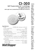
Keyhole slots
(for mounting to
4" octagonal box)
Double gang
mudring
mounting holes
Light level
pushbutton
DIP
switches
PIR lens
ON
1
2
3
4
5
6
7
ECE
PIR Activity
LED (Green)
Visit our website for FAQs: www.wattstopper.com


