


2
How It Operates
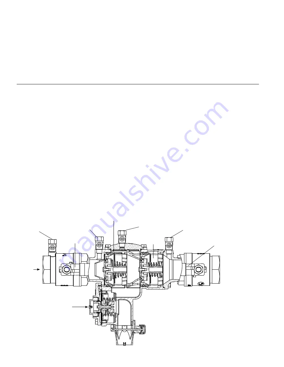
The FEBCO Series 860 Reduced Pressure Zone backflow preventer
assembly consists of two independently operating, spring loaded
check valves with a pressure differential relief valve located between
the two checks. The pressure drop across the first check valve
is approximately 7.0 psid with no flow. The relief valve consists of
a hydraulically balanced diaphragm with the high pressure side
hydraulically connected to the upstream pressure zone. The relief
valve remains closed during normal operation. The low pressure side
of the diaphragm is spring loaded to force the relief valve to open
when the pressure drop across the first check and the diaphragm is
reduced to approximately 3.0 psid. A complete assembly includes
two shutoff valves and four test cocks.
Service Procedures
FEBCO backflow prevention assemblies can be serviced with
standard tools and are designed for ease of maintenance. The
assemblies can be serviced in line, eliminating the need to remove
and reinstall a unit.
Suggested Tool Kit
• 1 crescent wrench
• 1 medium standard screwdriver
• Differential pressure test kit
• 1 medium Phillips screwdriver
• Box/open end wrench
1. Flush the line clean of debris before assembly installation. The
most common cause of check fouling and relief valve discharge is
dirt and debris in the seating areas.
2. To flush the line after installation, slowly close the inlet shutoff
valve, remove the cover and spring assemblies of both check
valves, and open the inlet shutoff valve to allow sufficient flow
of water through the assembly. Clear all sand, debris, and other
particles from the line. If debris in the water continues to cause
fouling, consider installation of a strainer upstream of the assembly
if in compliance with local codes.
3. Rinse all parts with clean water before reassembly.
4. Carefully inspect diaphragms, seals, and seating surfaces for
damage or debris. If the check valve seat disc has been severely
cut at the seat ring diameter, the assembly has been subjected
to extremely high and repeated backpressure. Either thermal
water expansion or water hammer is the most likely cause. If
backpressure persists, consider installation of a pressure relief
valve downstream of the assembly.
5. Use caution to avoid damaging any guiding surfaces while
handling parts. Do not force parts together. The O-ring seals
used in FEBCO assemblies require only a small tightening force to
ensure a positive seal.
6. Test the unit after servicing in accordance with locally approved
test methods to ensure proper operation; see the "Testing"
section.
7. Use the exploded drawings and parts list for visual aid information;
see the "Parts" section.
8. Apply a thin coating of the lubricant supplied in the repair kit to the
O-rings and other seals as directed. Any additional lubricants in
use must be FDA Approved food-grade petroleum jelly.
Test Cock No. 3
Test Cock No. 4
2nd Check
Module
Relief Valve
Test Cock No. 1
Inlet Shutoff
Valve
Outlet Shutoff
Valve
1st Check Module
Flow
Test Cock No. 2
Cross-section with flood sensor
(Union ball valves not shown)


