


10
Troubleshooting
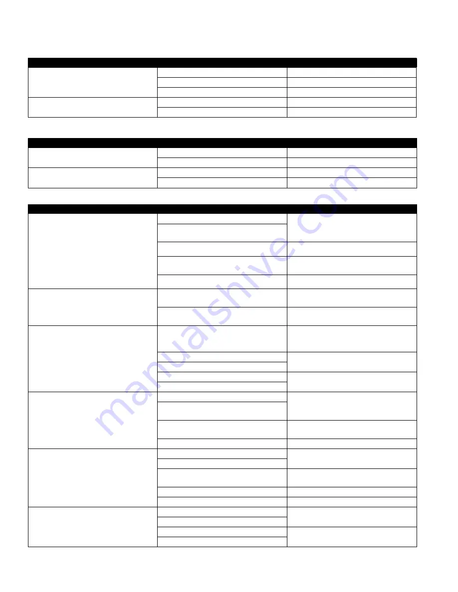
Check Procedure with Differential Pressure Gauge
CHECKLIST
READING
PROBLEM
Check differential across check valve No. 1
2 to 3 psid
Leak in check valve No. 1 or No. 2
6 to 8 psid and steady
Malfunctioning pressure relief valve
2 to 7 psid and steady
Inlet pressure fluctuating
Check differential across check valve No. 1
2 to 3 psid
Check valve No. 1 held open
6 to 8 psid and steady
Malfunctioning pressure relief valve
Check Procedure Without Differential Pressure Gauge
CHECKLIST
READING
PROBLEM
Close gate valve No. 2
If discharge stops
Leak in check valve No. 2
If discharge does not stop
Try the next remedy
Open test cock No. 4 to produce a flow greater than the
differential relief valve discharge
If discharge stops
Leak in check valve No. 1
If discharge does not stop
Malfunctioning pressure relief valve
PROBLEM
CAUSE
SOLUTION
Continuous discharge from relief valve during NO FLOW
conditions (Discharge stops with water flow) With this
symptom, the pressure drop across check valve No. 1
would be 2 to 3 psid. If a flow of water (more than dis-
charge) is created through the valve, the pressure drop
should increase to approximately 7 psi
Debris fouling check valve No. 1
Inspect and clean
Outlet pressure highter than inlet pressure and deris
fouling check valve No. 2
Spring stem not moving freely
Inspect for dirt or other foreign material
Damaged seat or seat disc
Inspect and replace (If necessary, the seat disc can be
reversed in sizes ½" to 2".)
Leakage at check module O-ring
nspect and replace seal or O-ring
Intermittent discharge from relief valve during NO FLOW
conditions. With the symptom, the pressure drop across
the check valve No. 1 would vary from about 2 to 7 psid
Inlet line pressure variations causing relief valve to
discharge
Eliminate or reduce pressure variations by installing a soft-
seated, spring-loaded check on upstream side of device
Pressure surges (water hammer) causing relief valve to
discharge as pressure wave passes through the zone
Eliminate or reduce pressure surges
Continuous discharge from relief valve during FLOW and
NO FLOW conditions With this symptom, the pressure drop
across the check valve No. 1 would be 7 psid or more at
all time
Seat disc dislodged from cavity in the main stem
(This can be caused by pressure surges during initial
filling of system lines.)
Reposition disc in main stem cavity
Repressurize system slowly
Debris fouling the relief valve seat
Inspect and clean
Debris blocking the relief valve sensing passage
Dirt or scale jamming main stem
Inspect and clean, or replace
Leakage at main stem
Relief valve does not open above
2.0 psid during field testing
Outlet gate valve not closed completely
Inspect and clean
Plugged low pressure hydraulic passage (from “ZONE” to
inner diaphragm)
Improper alignment of internal parts during reassembly
(causing high resistance to movement)
Reassemble
Jammed main stem due to debris blocking gate valve
Clean
Check No. 1 pressure drop is low (less than 5 psid) during
field testing
Debris fouling first check seat
Inspect and clean
Debris fouling second seat with backpressure
Inlet pressure variations causing inaccurate gauge reading
Eliminate pressure variations by installing a soft-seated,
spring-loaded check on upstream side of device
Damaged seat or seat disc
Inspect and clean as required
Worn guide, bushing, or stem
Inspect and replace as required
Check No. 2 fails to hold back pressure during field testing
Outlet gate valve not closed completely
Inspect and clean
Debris fouling second check seat
Damaged seat or seat disc
Inspect and replace if required
Worn guide, bushing, or stem


