background image

3

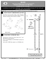
Check Module Disassembly

The complete list of items is included in the "Parts" section.
1. Slowly close the inlet and outlet ball valves. Bleed residual 

pressure by opening test cocks No. 2, No. 3, and No. 4. Allow the 

test cocks to remain open until the reassembling is completed. 

Test cock No. 1 should remain closed.

2. Remove the cover bolts (Item 21) using the appropriate size 

wrench.

3. Remove the spacer (Item 8) by grasping the flanged end of the 

spacer and pulling it straight up.pulling straight up.

4. Remove the inlet check assembly by pulling it in the direction of 

flow from the body bore until it is completely exposed, then lift it 

out of the body.

5. Remove the outlet check assembly by placing the tip of a 

medium-sized, flat-nose screwdriver in the slot of the seat  

(Item 3) and prying the check assembly back until the red O-ring 

(Item 3.1) is exposed. Then, using fingers, pull it from the body 

bore until it is completely exposed, then lift it out of the body.

Check Module Seal Replacement

Both check assemblies are disassembled and reassembled in the 

same manner. To service the checks, replace the check modules 

with new ones by using check module assembly kits available from 

FEBCO. Or, replace the rubber components in the check modules 

by using the replacement rubber parts kits.
1. To disassemble the unit, grasp the seat section (Item 3) in one 

hand and the guide section (Item 7) in the other hand, then rotate 

in a counterclockwise direction (approx. 1/8 turn) until the two 

parts disengage.

2. Remove the retaining screw (Item 5.2) and disc retainer (Item 5.1) 

so the rubber disc is fully exposed. Carefully pry out the rubber 

disc from the poppet. Be careful not to damage the poppet when 

removing the disc. Rinse the poppet in clean water and replace 

the old rubber disc with a new rubber disc. If the rubber disc is not 

damaged, it can be reversed and reinstalled when a new disc is 

unavailable. Rinse all other internal components with clean water. 

Replace the disc retainer and secure with the retaining screw (Item 

5.2).

3. Reassemble the check module by reversing the preceding steps. 

When reassembling the check module, insert the poppet stem 

into the guide hole and keep fingers clear of the slots in the 

module.

Содержание FEBCO 860 Series

Страница 1: ...s to discourage tampering or install a protective enclosure to discourage vandals When opting for an enclosure install the protective cover so that adequate clearance is available for maintenance and...

Страница 2: ...ng assemblies of both check valves and open the inlet shutoff valve to allow sufficient flow of water through the assembly Clear all sand debris and other particles from the line If debris in the wate...

Страница 3: ...semblies are disassembled and reassembled in the same manner To service the checks replace the check modules with new ones by using check module assembly kits available from FEBCO Or replace the rubbe...

Страница 4: ...e from the relief valve assembly may not indicate a relief valve failure Water is discharged from the relief valve when the mainline check valves become fouled with foreign debris For more information...

Страница 5: ...may become folded or creased if the internal assembly is restricted while tightening the cylinder 7 Replace the O ring Item 20 in the relief valve cover Properly seat the round bead on the large diaph...

Страница 6: ...certain conditions relief valves can discharge water at rates greater than the air gap drain capacity 2 For an indoor installation locate the assembly near a floor drain sized to adequately handle dis...

Страница 7: ...Seat Ring RV 1 12 1 Gasket Ring RV 1 13 Spring RV 1 14 Seat Disc RV 1 15 Diaphragm RV 1 16 Outer Diaphragm RV 1 17 Small Piston RV 1 17 1 Round HD Screw RV 1 17 2 Washer RV 1 17 3 Hex Nut RV 1 18 Cyl...

Страница 8: ...1 1 4 2 32 50 Both checks Kit includes Items 2 2 3 1 qty 2 and 5 qty 2 Relief Valve Rubber Kit 905345 ALL 1 2 3 4 15 20 905345 ALL 1 25 905346 ALL 1 1 4 2 32 50 Kit includes Items 12 12 1 14 15 16 18...

Страница 9: ...se the outlet ball valve After clearing the system with air partially open the outlet ball valve 7 Leave all drain valves test cocks and ball valves in the half open half closed position for the winte...

Страница 10: ...line pressure variations causing relief valve to discharge Eliminate or reduce pressure variations by installing a soft seated spring loaded check on upstream side of device Pressure surges water hamm...

Страница 11: ...capabilities to the relief valve of an existing installation in a BMS configuration For Cellular Communication ORDERING CODE ADD ON RETROFIT KIT DESCRIPTION 88009432 FP FBF CFS Cellular Flood Sensor C...

Страница 12: ...damaged if this product does not work properly other costs resulting from labor charges delays vandalism negligence fouling caused by foreign material damage from adverse water conditions chemical or...

Отзывы: