8
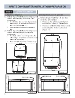
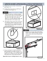
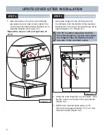
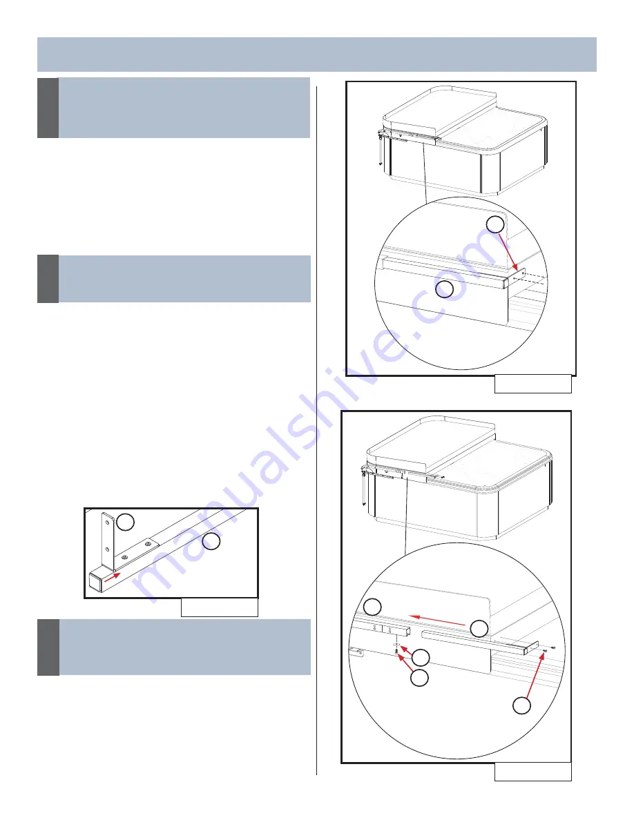
3. Slide Extension Tube Assy.(M) into Side
Assembly Channel until Angle Bracket (R) is
fl ush against the cover as shown in (Figure
4.3).
UPRITE COVER LIFTER INSTALLATION
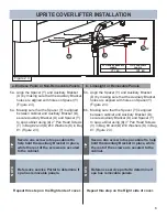
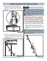
5. Tighten the 1/4” Hex Head Bolt (Q) and
Washer (W) with 7/16” wrench below the
Side Assembly Channel (C) to secure the
Extension Tube (M) to the Side Assembly
Channel (C). See (Figure 4.4).
Repeat this step on the Right side of cover.
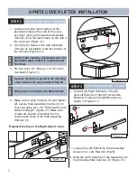
Figure 4.3
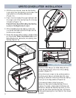
3. With Angle Bracket (R) fl ush against the
cover, mark and pre-drill holes 1/8” (3mm)
by 1/8”(3mm) deep (2 holes) into the cover
using the Angle Bracket (R) as a template as
shown in (Figure 4.3).
If the Extension tube does not easily
slide into the Side Assembly Channel,
check the Side Assembly Channel
mounting screws for interference.
NOTE
WARNING! RISK OF INJURY.
CLEAN ALL FINE METALLIC CHIPS THAT FALL
OUT OF PRE-DRILLED HOLES.
When pre-drilling holes, clean up all metal
chips that may come out of holes. If not cleaned
these metal chips can go into the water and
cause injury.
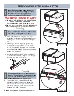
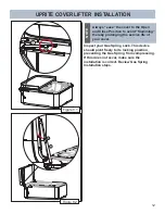
3. Secure Angle Bracket (R) to cover using (2)
of the Pan Head Screws (Figure 4.4). Bag #1
(S) (#10 1/2” Pan Head screws).
4
67
Figure 4.4
S
C
2X
W
M
Q
Make sure that the cover set is folded in
half before starting this next step.
NOTE
If a gap exist between cover and Angle
Bracket (R), reposition the angle bracket
on both Left and Right Extension Tube
Assemblies as see in (Figure 3.4).
NOTE
R
M
Figure 4.2
5
6
M
R
Содержание UPRITE
Страница 15: ...14 NOTES ...
Страница 16: ...62732 D 01 20 ...

