10
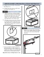
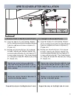
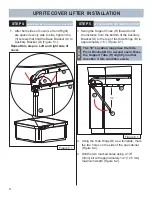
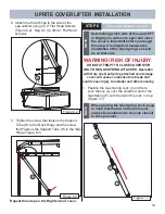
5. Tighten the screw that fastens the Support
Tube (H) to the Deck Hinge and the screw
that Fastens the Support Tube (H) to the Side
Hinge Figure 6.3)
Figure 6.3
H
Figure 6.2
U
H
B
2X
Repeat this step on the Right side of cover.
UPRITE COVER LIFTER INSTALLATION
STEP 6
ATTACH GAS SPRING TO LIFTER
Determining which side of the spa (LEFT
or Right) you will use to open and close
the cover is important before you begin
this step. It is important because the
Installation of the Gas Spring Lock will
be on that side.
NOTE
WARNING! RISK OF INJURY.
DO NOT ATTEMPT TO CLOSE COVER WITH
ONLY ONE GAS SPRING ATTACHED. Operation
with Only one Gas Spring attached can damage
cover, will cause components to break and
could cause injury to installer and others nearby.
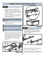
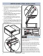
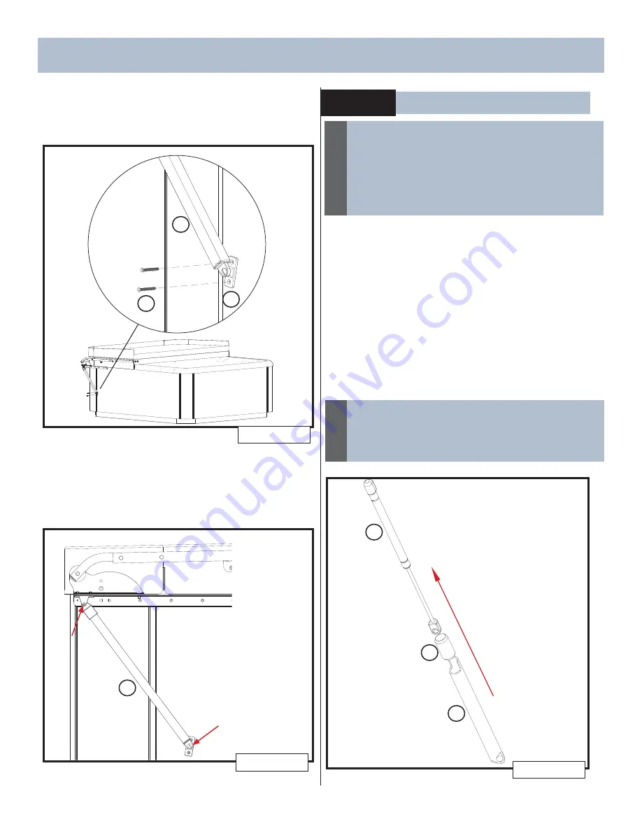
1. Position the Gas Spring Lock (I) and Sure
Lock Sleeve (L) over the small rod end of the
Gas Spring (F) with the tab of the lock on top
(Figure 7.1)
I
L
F
Figure 7.1
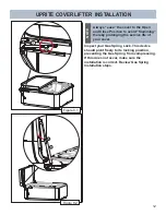
When placing the Gas Spring Lock, keep
in mind that the tab on the lock must
always be positioned to the side closest
to the spa cover.
NOTE
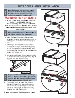
2. Attach the Side Hinge to the side of the
spa cabinet using (2) 2” Flat Head Screws
(Figure 6.2). Bag # 2 (U) (#10 2” Flat Head
screws).
4
Содержание UPRITE
Страница 15: ...14 NOTES ...
Страница 16: ...62732 D 01 20 ...

