background image

3

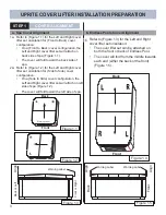
UPRITE COVER LIFTER INSTALLATION PREPARATION

STEP 1

COVER ALIGNMENT

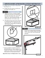
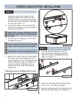
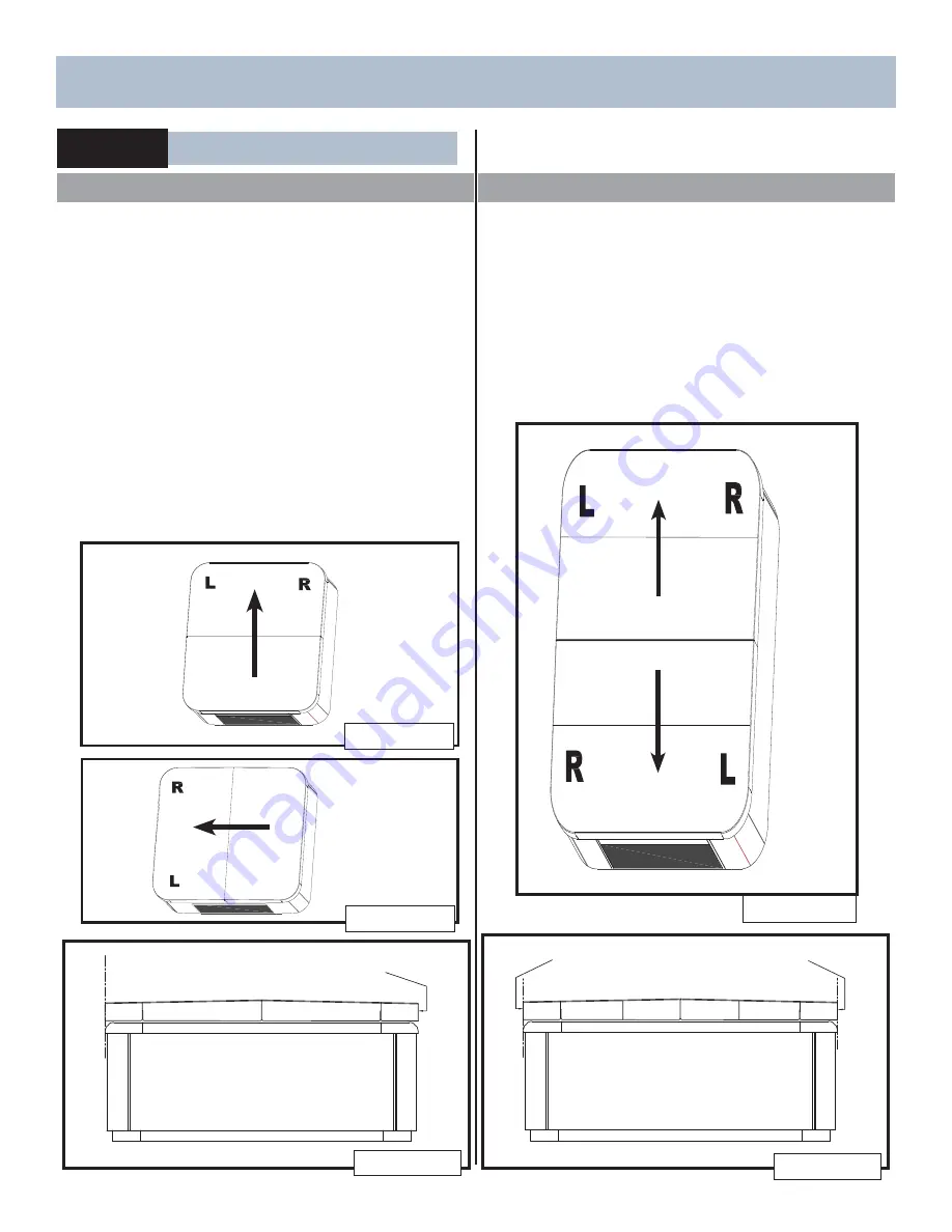
1.  Refer to (Figure 1.1) for the Left and Right cover 

lifter set orientation for (Front to Back) cover 
confi guration:  
•  On a (Front to Back) cover confi guration, the 

Left and Right cover lifter set will attach on 
back side of spa (Figure 1.1).

•  The cover will fold toward the back side of 

spa.


Back

Figure 1.5

Front

Warning Label

Align

Warning Label

Figure 1.4

a. Spa Cover Alignment

b. Endless Pools Cover Alignment

Front

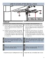
1.  Refer to (Figure 1.3) for the Left and Right 

cover lifter set orientation:
•  The cover lifter set can be attached on 

both the front or back of Endless Pool. 

•  The cover will fold from the middle towards 

each end (either the back or the front) 
(Figure 1.5).

1a.

1b.

Figure 1.2

Front

Back

Figure 1.3

Warning Label

Align

1.  Refer to (Figure 1.2) for the Left and Right cover 

lifter set orientation for (Side to Side) cover 
confi guration:  
•  On a (Side to Side) cover confi guration, the 

Left and Right cover lifter set will attach on left 
side of spa (Figure 1.2).

•  The cover will fold toward the left side of spa. 

2

Warning Label

Align

Figure 1.1

Back

W

arning Label

a.

Back or Left

Front or Right

Содержание UPRITE

Страница 1: ...OVER LIFTER INSTALLATION 7 ATTACH SIDE ASSY CHANNEL COVER LIFTER INSTALLATION 8 ASSEMBLE EXTENSION TUBE ASSY ATTACH EXTENSION TUBE TO COVER COVER LIFTER INSTALLATION 9 ATTACH SUPPORT TUBE TO CABINET COVER LIFTER INSTALLATION 10 ATTACH GAS SPRING TO BASE BRACKET COVER LIFTER INSTALLATION 11 LOCKING MECHANISM COVER LIFTER INSTALLATION 13 COVER ANGLE ADJUSTMENT NOTES 14 TABLE OF CONTENTS Of your UPRI...

Страница 2: ...uare Pan Head Bag 2 F 2 Gas Spring 60 LB U 4 10 X 2 Square Flat Head Bag 2 G 2 Angle Bracket V 10 10 X 3 Square Pan Head Bag 3 H 1 Support Tube W 2 X 1 X 1 8 Thick Washer Bag 1 I 1 Gas Spring Lock X 1 Orange Label Bag 1 K 10 10 Flat Washer Bag 1 Y 2 Spacer 0 75 x 1 x 17 Spacer Bag 4 N A 2 EXTRA DECK HINGES W SLOTTED BOLTS Z 2 Spacer 0 25 x 1 25 x 9 Spacer Bag 5 2 Pcs of Extra Hardware A B C D E F ...

Страница 3: ...ere must be a minimum of 7 clearance between the wall and the retracting side of the spa for cover to operate properly and 3 on each side for Side Arm clearance NOTE Consider spa cover wind skirt length when considering installation of cover lifter The Warning Label is always on the front of the cover the lifter will attach on either the back side of the spa or the left side of spa depending on co...

Страница 4: ...ront 1 Refer to Figure 1 3 for the Left and Right cover lifter set orientation The cover lifter set can be attached on both the front or back of Endless Pool The cover will fold from the middle towards each end either the back or the front Figure 1 5 1a 1b Figure 1 2 Front Back Figure 1 3 Warning Label Align 1 Refer to Figure 1 2 for the Left and Right cover lifter set orientation for Side to Side...

Страница 5: ... set Figure 1 7 Figure 1 6 Back Hidden Aluminum Plate 1 Position the cover evenly on all spa sides See Figure 1 3 5 Loosen the 3 screws that hold the Base Bracket A to Auxiliary Bracket D Figure 1 8 Do this to both Left and Right Side Assembly STEP 3 BASE BRACKET TO AUXILIARY BRACKET 1 3a Figure 1 8 H Figure 1 7 1 Using your finger to locate the aluminum plate illustrated by a square Figure 1 6 for...

Страница 6: ...ax into spa cabinet Figure 2 2 H 1 Place a straight edge ruler under the spa shell lip on the back left part of the spa Align the back of the Auxiliary Bracket D with the straight edge ruler Figure 2 2 2 While holding in place the straight edge ruler aligned with the back side of Auxiliary Bracket D and using the small holes on the Auxiliary Bracket D mark 4 holes Mark the holes starting from the ...

Страница 7: ...vable Panels 4 Align the Spacer Y and Auxiliary Bracket D by making sure that the Auxiliary Bracket holes are aligned with holes on Spacer Y Figure 2 3 4 Making sure that the Spacer Y is aligned between cabinet and Auxiliary Bracket D secure Auxiliary Bracket D and Spacer Y to spa cabinet using 4 3 Pan Head Screws V in Bag 3 and 4 10 Washers K in Bag 1 Figure 2 3 7 b b 5 6 Secure one screw into sp...

Страница 8: ...ill holes 1 8 3mm by 1 2 12 5 mm max depth Figure 3 1 All 4 holes must be positioned over the aluminum plate which is located under the Vinyl NOTE Figure 3 2 C R 4X D Figure 3 1 Z C Repeat this step on the Right side of cover 1 Make sure to align Channel C and Spacer Z secure Side Assembly Channel C to cover set using 4 1 1 2 Flat Head Screws located in Bag 1 Figure 3 1 Make sure screws are seated...

Страница 9: ...If the Extension tube does not easily slide into the Side Assembly Channel check the Side Assembly Channel mounting screws for interference NOTE WARNING RISK OF INJURY CLEAN ALL FINE METALLIC CHIPS THAT FALL OUT OF PRE DRILLED HOLES When pre drilling holes clean up all metal chips that may come out of holes If not cleaned these metal chips can go into the water and cause injury 3 Secure Angle Brac...

Страница 10: ... this condition exists NOTE 2 Using the Side Hinge B as a template mark the two holes on the side of the spa cabinet Figure 6 2 3 Drill the two marked holes using a 1 8 3mm bit with approximately 1 2 12 5 mm maximum depth Figure 6 2 5 After both sides of cover Left and Right are spaced evenly side to side tighten the 3 screws that hold the Base Bracket A to Auxiliary Bracket D Figure 5 1 STEP 4 BA...

Страница 11: ...ck will be on that side NOTE WARNING RISK OF INJURY DO NOT ATTEMPT TO CLOSE COVER WITH ONLY ONE GAS SPRING ATTACHED Operation with Only one Gas Spring attached can damage cover will cause components to break and could cause injury to installer and others nearby 1 Position the Gas Spring Lock I and Sure Lock Sleeve L over the small rod end of the Gas Spring F with the tab of the lock on top Figure ...

Страница 12: ...he Base Bracket A above the non locking Gas Spring Figure 7 4 Figure 7 2 F H B A STEP 7 LOCKING MECHANISM The Sure lock Sleeve L slides along the top of the Gas Spring F when it is in free sliding position Figure 8 1 When the cover is open in the vertical position the Sure Lock Sleeve will slide down the Gas Spring F and rest on the top of the Gas Spring Lock I in a locking position Figure 8 2 The...

Страница 13: ...eby prolonging the service life of your cover NOTE Inspect your Gas Spring Lock This device should pivot freely to its locking position preventing the Gas Spring from compressing If this does not occur make sure the installation is correct Review Gas Spring Installation steps UPRITE COVER LIFTER INSTALLATION ...

Страница 14: ...ght side assembly 1b While the cover is in full open position use a small flat head screwdriver to slightly pry on the back of the gas spring end to release the gas spring from the Assy Channel Ball Stud Bracket C1 Figure 9 2 2b Swing the gas spring F out of the way Figure 9 2 3b Follow steps 1a thru 3a on this page to adjust the fully open position angle of your cover Figure 9 1 1a Find the two bo...

Страница 15: ...14 NOTES ...

Страница 16: ...62732 D 01 20 ...

Отзывы: