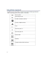
1-4
System Overview
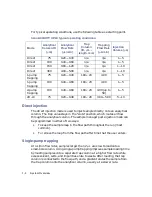
For typical operating conditions, use the following table as a starting point.
Direct injection
The direct injection mode is used to inject sample directly onto an analytical
column. The trap valve stays in the “elute” position, which routes all flow
through the analytical column. The sample manager post-injection mode can
be programmed in either of two ways:
•
To keep the sample loop in the flow path throughout the run (most
common).
•
To remove the loop from the flow path after time that the user enters.
Single-pump trapping
At nL/min flow rates, samples larger than 2
µ
L are slow to load onto a
small-bore column. Using single-pump trapping improves sample loading time
by loading samples onto a separate trap column at a higher flow rate while
excess solvent, salts, and impurities elute to waste. After loading, the trap
column is connected to the flow path, and a gradient elutes the sample from
the trap column onto the analytical column, usually at a slower rate.
nanoACQUITY UPLC typical operating conditions:
Mode
Analytical
Column ID
(
µ
m)
Analytical
Flow Rate
(
µ
L/min)
Trap
Column
(ID,
µ
m
×
length, mm)
Trapping
Flow Rate
(
µ
L/min)
Injection
Volume (
µ
L)
Direct
75
0.20—0.40
n/a
n/a
1—5
Direct
100
0.40—0.60
n/a
n/a
1—5
Direct
150
0.80—1.20
n/a
n/a
1—10
Direct
300
4.00—5.00
n/a
n/a
1—10
1-pump
trapping
75
0.20—0.40
180
×
20 4.00
1—5
1-pump
trapping
100
0.40—0.60
180
×
20 4.00
1—5
2-pump
trapping
100
0.40—0.60
180
×
20
4.00 (up to
50)
1—5
2D-LC
75
0.20—0.40
180
×
20 3.00—5.00 5—10
Содержание nanoACQUITY UPLC
Страница 7: ...vii ...
Страница 16: ...xvi ...
Страница 20: ...xx Table of Contents ...
Страница 32: ...1 12 System Overview ...
Страница 58: ...2 26 Preparing System Hardware ...
Страница 76: ...4 12 Verifying System Operation ...


