background image

2-11

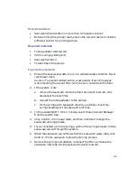
Prime A/B Solvents dialog box:

3.

Select solvent A1 or B1.

4.

In the Time (min) box, specify the number of minutes from 0.10 through 
999.99. The default value is 1.0 minute. 

Recommendation:

 2.0 minutes.

5.

Click Start.

6.

When finished, repeat as needed for B1 and for all solvents in use. 

Содержание nanoACQUITY UPLC

Страница 1: ...nanoACQUITY UPLC System Quick Start Guide 71500097503 Revision D Copyright Waters Corporation 2006 All rights reserved C O R P O R A T I O N ...

Страница 2: ...urate at the time of publication In no event shall Waters Corporation be liable for incidental or consequential damages in connection with or arising from the use of this document Trademarks Millennium and Waters are registered trademarks and ACQUITY UPLC Atlantis BEH Technology Empower MassLynx MassPREP nanoACQUITY UPLC and Symmetry are trademarks of Waters Corporation CTC PAL is a trademark of C...

Страница 3: ...tions suggestions for improvements or find errors in this document Your comments will help us improve the quality accuracy and organization of our documentation You can reach us at tech_comm waters com Waters Corporation 34 Maple Street Milford MA 01757 USA ...

Страница 4: ...tilisateur à exploiter l équipement Achtung Jedwede Änderungen oder Modifikationen an dem Gerät ohne die ausdrückliche Genehmigung der für die ordnungsgemäße Funktion stüchtigkeit verantwortlichen Personen kann zum Entzug der Bedienungsbefugnis des Systems führen Avvertenza eventuali modifiche o alterazioni apportate a questa unità e non espressamente approvate da un ente responsabile per la confo...

Страница 5: ...e l instrument Evitez d utiliser des tubes sévèrement déformés ou endommagés Evitez d utiliser des tubes non métalliques avec du tétrahydrofurane THF ou de l acide sulfurique ou nitrique concentré Sachez que le chlorure de méthylène et le diméthylesulfoxyde entraînent le gonflement des tuyaux non métalliques ce qui réduit considérablement leur pression de rupture Vorsicht Bei der Arbeit mit Polyme...

Страница 6: ...iamento nei tubi non metallici riducendo notevolmente la resistenza alla rottura dei tubi stessi Advertencia se recomienda precaución cuando se trabaje con tubos de polímero sometidos a presión El usuario deberá protegerse siempre los ojos cuando trabaje cerca de tubos de polímero sometidos a presión Si hubiera alguna llama las proximidades No se debe trabajar con tubos que se hayan doblado o some...

Страница 7: ...vii ...

Страница 8: ...e défectueuses Vorsicht Der Benutzer wird darauf aufmerksam gemacht dass bei unsach gemäßer Verwenddung des Gerätes unter Umständen nicht ordnungsgemäß funktionieren Attenzione l utente deve essere al corrente del fatto che se l apparecchia tura viene usta in un modo specificato dal produttore la protezione fornita dall apparecchiatura potrà essere invalidata Advertencia el usuario deberá saber qu...

Страница 9: ...fin d éviter tout risque d incendie Vorsicht Zum Schutz gegen Feuergefahr die Sicherungen nur mit Sicherungen des gleichen Typs und Nennwertes ersetzen Attenzione per una buona protezione contro i rischi di incendio sostituire i fusibili con altri dello stesso tipo e amperaggio Advertencia sustituya los fusibles por otros del mismo tipo y características para evitar el riesgo de incendio ...

Страница 10: ...nt d effectuer la mainte nance de l instrument Vorsicht Zur Vermeidung von Stromschlägen sollte das Gerät vor der Wartung vom Netz getrennt werden Attenzione per evitare il rischio di scossa elettrica scollegare il cavo di alimentazione prima di svolgere la manutenzione dello strumento Precaución para evitar descargas eléctricas desenchufe el cable de alimen tación del instrumento antes de realiza...

Страница 11: ...d Warning or Caution these are the safety precaution symbols you might encounter on instruments and or in documents Warning Indicates a potential health or safety hazard Refer to the manual Warning Indicates hazardous voltages can exist Warning Indicates hot surfaces or high temperatures can exist Warning Indicates danger from needle stick punctures Warning Indicates danger from ultraviolet radiat...

Страница 12: ...ter the following symbols and labels on packaging instruments and or in documents Direct current Alternating current Protective conductor terminal Frame or chassis terminal Fuse Electrical power on Electrical power off Keep upright Keep dry Fragile handle contents with care l ...

Страница 13: ...erence to radio communications However there is no guarantee that interference will not occur in a particular installation If this equipment does cause harmful interference to radio or television reception which can be determined by turning the equipment off and on the user is encouraged to try to correct the interference by one or more of the following measures Reorient or relocate the receiving ...

Страница 14: ...ety and electromagnetic requirements of the European community Display of the CE mark indicates compliance to these requirements The safety requirements are set forth via the standard EN61010 Safety requirements for electrical equipment for measurement control and laboratory use Part 1 General requirements The EMC requirements are supported in the standard EN61326 Electrical equipment for the meas...

Страница 15: ...s as potentially infectious Precautions are outlined in CDC Guidelines on Specimen Handling CDC NIH Manual 1984 Calibration Follow acceptable methods of calibration with pure standards to calibrate methods Use a minimum of five standards to generate a standard curve The concentration range should cover the entire range of quality control samples typical specimens and atypical specimens Quality con...

Страница 16: ...xvi ...

Страница 17: ...ralia emissions requirements xiv nanoACQUITY UPLC system information xv Intended use xv Biological hazard xv Calibration xv Quality control xv 1 System Overview 1 1 Instruments and components 1 1 nanoACQUITY operating modes 1 3 Direct injection 1 4 Single pump trapping 1 4 Two pump trapping 1 5 Two dimensional liquid chromatography 2D LC 1 5 nanoACQUITY binary solvent manager 1 6 How the binary so...

Страница 18: ... LED 2 2 Status LEDs 2 3 Preparing the auxiliary solvent manager 2 4 Priming the seal wash 2 5 Preparing the binary solvent manager 2 8 Priming the seal wash 2 8 Priming the binary solvent manager 2 10 Preparing the sample manager 2 12 Selecting weak and strong wash solvents 2 12 Priming the sample manager 2 14 Washing the sample manager needle 2 15 Characterizing the needle seal 2 17 Characterizi...

Страница 19: ...3 Configuring System Software 3 1 Configuring MassLynx 3 1 Starting the nanoACQUITY UPLC Console from MassLynx 3 5 Configuring events 3 6 4 Verifying System Operation 4 1 Required materials 4 1 Preparing the mobile phases 4 2 Preparing the sample 4 3 Preparing the system 4 4 Creating the test methods 4 6 Creating the instrument method 4 6 Performing the test 4 10 ...

Страница 20: ...xx Table of Contents ...

Страница 21: ...nents Binary solvent manager with flow control modules Auxiliary solvent manager for NanoLockSpray lock mass addition and two pump trapping with flow control module Sample manager and heating and trapping module which holds the analytical column Contents Topic Page Instruments and components 1 1 nanoACQUITY operating modes 1 3 nanoACQUITY binary solvent manager 1 6 Auxiliary solvent manager 1 7 Sa...

Страница 22: ...0 20 and 5 00 µL min With open loop control and nanoACQUITY UPLC columns of internal diameters ranging from 75 µm to 1 mm the nanoflow rates can extend to 100 µL min The column hardware and the matched outlet tubing can withstand up to 69 000 kPa 690 bar 10 000 psi The column dimensions allow optimal MS compatible flow rates and matched outlet tubing minimizes the effect of extra column volume Sol...

Страница 23: ...TY system can operate in direct injection mode or any of four trapping modes Trapping improves system performance in several ways Removes salts Cleans samples Concentrates larger sample volumes Decreases sample loading time Each mode requires a different configuration of solvent managers and columns Direct injection mode uses the binary solvent manager with an analytical column Single pump trappin...

Страница 24: ...gle pump trapping improves sample loading time by loading samples onto a separate trap column at a higher flow rate while excess solvent salts and impurities elute to waste After loading the trap column is connected to the flow path and a gradient elutes the sample from the trap column onto the analytical column usually at a slower rate nanoACQUITY UPLC typical operating conditions Mode Analytical...

Страница 25: ... sample manager to elute various portions of the sample off the ion exchange column and onto a trap column At that point separation and analysis proceeds as in two pump trapping Two dimensional liquid chromatography can increase the amount of information from complex proteomics samples reducing their complexity and dynamic range prior to mass spectrometry MS analysis To further improve the identif...

Страница 26: ...flows to the sample manager To create gradients and mixtures the chromatography software controls the two solvents mixing ratio by varying the flow of pump A relative to that of pump B A pressure transducer in each pump head relays pressure data to the solvent manager whose firmware measures pump head pressures during the pumping cycle Thus the solvent manager adjusts the precompression to ensure ...

Страница 27: ...anol The flow control module s mass flow sensor measures the flow from the pump The auxiliary solvent manager monitors the output and adjusts the solvent flow accordingly for precise flow from 0 20 to 5 00 µL min Sample manager The sample manager injects the samples it draws from microtiter plates or vials into the chromatographic flow stream In maximum throughput mode the sample manager can perfo...

Страница 28: ...rtial loop 1 1 1 9 Partial loop with needle overfill Not applicable Not applicable Not applicable Full loop Auto 2 4 2 1 Overfill 2 2 2 2 Overfill 2 4 2 3 Overfill 2 6 2 Loop 5 µL Needle 15 µL Partial loop 2 2 4 9 Partial loop with needle overfill 2 6 3 8 Full loop Auto 5 10 5 1 Overfill 5 5 5 2 Overfill 5 10 5 3 Overfill 5 15 5 Loop 10 µL Needle 15 µL Partial loop 5 5 9 5 Partial loop with needle...

Страница 29: ... 180 In the 0 home position the column tray is directly above the sample manager and can be connected to an optional optical detector In the 180 away position the analytical column can be plumbed into a mass spectrometer located on the system s right Loop 20 µL Needle 15 µL Partial loop 5 5 19 Partial loop with needle overfill 5 9 15 Full loop Auto 10 40 20 1 Overfill 10 20 20 2 Overfill 10 40 20 ...

Страница 30: ...orbance detector the TUV detector operates from 190 to 700 nm Its light guiding flow cell is intended for high sensitivity chromatography with high peak capacity The detector controlled by MassLynx software for LC MS applications operates as an integral part of the system Mass detectors The nanoACQUITY UPLC system acts as a mass spectrometry inlet for nanoflow rate applications such as proteomics ...

Страница 31: ...s and small display screens traditionally found on the front of system hardware As such it provides a convenient way to configure settings monitor performance run diagnostic tests and maintain the system and its modules From the software s Web like interface you can quickly navigate to visual representations of each system module and its components You can also navigate to interactive diagrams whi...

Страница 32: ...1 12 System Overview ...

Страница 33: ...h module beeps three times and runs a series of startup tests Full initialization usually requires about seven minutes Contents Topic Page Powering on the system 2 1 Monitoring startup tests 2 2 Monitoring the LEDs of system instruments 2 2 Preparing the auxiliary solvent manager 2 4 Preparing the binary solvent manager 2 8 Preparing the sample manager 2 12 Preparing the detector 2 21 Conditioning...

Страница 34: ... detector s lamp LED shows steady green 2 Power on the workstation You can monitor the nanoACQUITY UPLC Console for messages and visual signals 3 Start MassLynx Monitoring startup tests These startup tests run when you power on the workstation CPU board Memory RAM and ROM External communication system Ethernet Clock Monitoring the LEDs of system instruments Light emitting diodes LEDs on each syste...

Страница 35: ...es the module is currently idle Constant green Auxiliary and binary solvent managers Indicates the solvent manager is operating normally and solvent is flowing Sample manager Indicates the sample manager is operating normally attempting to complete any outstanding samples or diagnostic requests When sample and diagnostic requests are finished the LED reverts to the unlit mode Detector Indicates th...

Страница 36: ... to high organic content solvents For details see the nanoACQUITY UPLC System Operator s Guide Flashing red Indicates an error has stopped the module Look at the nanoACQUITY UPLC Console for information on the error that caused the failure Constant red Indicates a module failure that prevents further operation Power off the module and then power on If the LED is still constant red contact your Wat...

Страница 37: ...Waters has had success with Baker water and Fisher Optima acetonitrile It is important to flush the system with the appropriate solvents before passing eluent into the column optical detector and or mass spectrometer Your system is configured with the degassers removed from the fluidic pathway bypassed Only the weak and strong wash solvents are degassed Priming the seal wash Prime the seal wash in...

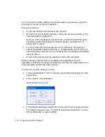
Страница 38: ...e the filter 2 If the system is dry a remove the seal wash inlet tube from the solvent reservoir and disconnect the inlet filter b connect the tubing adapter to the syringe c fill the syringe with seal wash solution and then connect the syringe assembly to the seal wash inlet tube 3 In the nanoACQUITY UPLC Console select Auxiliary Solvent Manager from the system tree 4 Click Control Prime seal was...

Страница 39: ...em or auxiliary solvent manager for use Running the system after it has been idle for more than four hours To prime the auxiliary solvent manager 1 In the nanoACQUITY UPLC Console select Auxiliary Solvent Manager from the system tree 2 Click Control Prime A B Solvents Prime A B Solvents dialog box 3 Select solvent B and then select B1 4 In the Time box specify the number of minutes from 0 10 throu...

Страница 40: ...p down list of the solvent manager s instrument method dialog box Priming the seal wash Prime the seal wash in the binary solvent manager to lubricate the plungers and flush away solvent and or any precipitated salts that have seeped past the plunger seals from the high pressure side of the piston chambers Prime the plunger seal wash under these conditions After using buffered mobile phase When th...

Страница 41: ...remove the seal wash inlet tube from the solvent reservoir and disconnect the inlet filter b connect the tubing adapter to the syringe c fill the syringe with seal wash solution and then connect the syringe assembly to the seal wash inlet tube 3 In the nanoACQUITY UPLC Console select Binary Solvent Manager from the system tree 4 Click Control Prime seal wash and then click Start to begin the seal ...

Страница 42: ...rom precipitating in the system introduce an intermediate solvent such as water when changing from buffers to high organic content solvents For details see the nanoACQUITY UPLC System Operator s Guide Recommendations Whenever you change solvents always purge and autozero the flow control module see the nanoACQUITY UPLC System Operator s Guide Ensure the solvent reservoirs contain enough solvent fo...

Страница 43: ...elect solvent A1 or B1 4 In the Time min box specify the number of minutes from 0 10 through 999 99 The default value is 1 0 minute Recommendation 2 0 minutes 5 Click Start 6 When finished repeat as needed for B1 and for all solvents in use ...

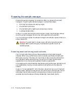
Страница 44: ...ting wash solvents Otherwise performance can be reduced specifically Area Height RSD and Linearity This does not mean that all other solvent combinations are prohibited Other combinations can be run with lower performance expectations or by manipulating default injection parameters Use a weak wash solvent based on the sample and mobile phase chemistries of your application making sure all solution...

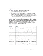
Страница 45: ...o your isocratic or initial gradient solvent conditions excluding buffers Do not use salt buffers in wash solvents Wash solvent effects Property Effect Organic species As a general principle strong and weak solvents should include the same organic species This might not always be practicable especially in the case of sticky samples You can however use a 100 organic strong wash solvent Solvent comp...

Страница 46: ...pping the priming sequence can leave strong solvent in the needle which can affect the chromatography Requirement The sample manager must be primed before you attempt to characterize the seal Sample diluent The weak wash solvent can contact the sample so match the weak wash solvent and sample matrix as closely as possible To offset adverse effects on peak shape caused by the matrix s composition a...

Страница 47: ...commends 5 to 7 cycles when you are changing solvents 5 Click OK Tip Each prime takes approximately 2 to 4 minutes 6 When the system status is Idle priming is finished Click Close Washing the sample manager needle Washing the needle is an optional procedure that flushes strong and or weak wash solvent through the needle and injection port Washing the sample manager needle removes contaminants from...

Страница 48: ...shes the needle with 200 µL of weak wash solvent after you use strong wash solvent You can increase but not decrease the default value of 200 µL Do not interrupt the priming sequence wait until it finishes Before you begin ensure that the solvents are compatible with your application that their volumes are sufficient and that the waste reservoir is large enough to contain the waste solvent To wash...

Страница 49: ...returns to Idle Click Close To stop a needle wash routine before it finishes From the sample manager information window click Control Reset SM Characterizing the needle seal The seal calibration procedure finds the position at which the needle obtains a seal within the wash station block The sample manager must be primed before starting this procedure Requirements Perform this procedure before cal...

Страница 50: ...ess of whether the sizes of the replacement parts are nominally the same as those of the original parts or differ from them Also perform this procedure when the composition of the weak wash solvent changes Characterizing the loop volume compares the loop s nominal volume to its measured volume Characterizing the needle volume compares the needle s nominal volume 15 0 µL to its measured volume Tip ...

Страница 51: ... the needle and loop sizes are correct 5 Click Close Loading sample plates in the sample manager The sample manager holds up to two ANSI SBS plates which you load through the front door The left plate is referred to as position 1 the right one as position 2 The nanoACQUITY UPLC Sample Manager SM supports ANSI sample plates and vial holders only The Sample Manager SM does not support vial plates wi...

Страница 52: ...ager until it clicks into place 5 Close the sample compartment door A mechanism on the door ensures the plates are positioned correctly when the door closes Caution The plates must be positioned correctly to avoid damaging the sample needle TP02389 A 1 well position Button Sample plate Plate tray ...

Страница 53: ...ly Tip The detector might not initialize correctly if the flow cell contains air 2 Press the power switch on the detector door The detector beeps three times and runs a series of startup tests while the lamp LED blinks Initialization requires approximately 2 minutes and lamp warm up requires approximately 3 minutes 3 When the lamp LED shows constant green start MassLynx You can monitor the nanoACQ...

Страница 54: ...he cell 4 Ensure the detector cell is filled with solvent and free of air bubbles Tip The detector might not initialize correctly if air is present in the cell 5 When both LEDs show constant green initialization is complete 6 Start the MassLynx software 7 To determine baseline values on the detector for future reference and to monitor lamp aging for decreased lamp output energy record the baseline...

Страница 55: ...rough it typically 10 column volumes and out to waste before connecting the column to the detector To condition the column 1 Remove the column inlet line from the detector and place the line s end in a small waste container 2 In MassLynx open the Sample Set window and select an inlet method that includes the chromatographic conditions you want to use 3 In the Samples table add an inlet prerun fiel...

Страница 56: ...ecessary for good retention time reproducibility 2 If a few hours will pass before the next injection slow the flow rate in the interim to a few tenths of a µL min to conserve solvent Tip Ensure that Auto Shutdown for your shutdown method is deactivated 3 Keep the detector operating and the heating and trapping module at operating temperature during this period Overnight or weekends To shut down t...

Страница 57: ...tem for 10 to 20 minutes at 10 µL min followed by isopropyl alcohol for another 10 to 20 minutes Then turn the pump off leaving isopropyl alcohol in the fluid lines Caution If any system modules are to be used for another type of analysis ensure that the liquids pumped initially through the system are miscible with methanol water methanol acetonitrile or isopropyl alcohol Likewise before restartin...

Страница 58: ...2 26 Preparing System Hardware ...

Страница 59: ...x 1 Select Start All Programs MassLynx MassLynx V4 1 Alternative You can also double click the MassLynx desktop shortcut If MassLynx Security is not enabled MassLynx starts and the MassLynx window appears If MassLynx Security is enabled the MassLynx Login dialog box appears 2 In the MassLynx Login dialog box type your user name and password and select your domain 3 Click OK Contents Topic Page Con...

Страница 60: ...3 2 Configuring System Software To select modules in the nanoACQUITY system 1 In the MassLynx window click Inlet Method Inlet Method window 2 Select Tools Instrument Configuration ...

Страница 61: ...ler dialog box select Waters Acquity and then click Next 7 In the Select Detector dialog box select Waters Acquity TUV as the detector if present and then click Next 8 Click Next Finish Finish To install the Instrument Control Option Pack 1 Click OK to start the Instrument Control Option Pack installation 2 Ensure that Install new instrument software or upgrade existing installation s is selected ...

Страница 62: ...en click Next A progress bar appears at the bottom of the dialog box Requirement You must select ACQUITY TUV Detector even if your system does not include a TUV detector If you do not do so the control will be blank when you open the nanoACQUITY UPLC Console 4 In the Results screen of the Instrument Control Option Pack dialog box click Finish Result The Inlet Method window appears ...

Страница 63: ... traditionally found on the fronts of system instruments It provides a convenient way to configure settings monitor performance run diagnostic tests and maintain the system To start the nanoACQUITY UPLC Console from MassLynx 1 In the MassLynx window click Inlet Method 2 Click the ACQUITY Additional Status tab ACQUITY Additional Status tab 3 Click Display console Result The nanoACQUITY UPLC Console...

Страница 64: ... 3 Click Events Triggering and then click Next 4 Select the check boxes that correspond to the event in and event out connections you made to the mass spectrometer Example If you connected the inject start terminals on the sample manager connector to the number 1 Event I P connector on the mass spectrometer select box 1 in the Event In section Choose Events dialog box 5 Click Next In the Configura...

Страница 65: ...uired materials Make sure these materials are on hand before you begin the verification test MS grade water acetonitrile Waters recommends Fisher Scientific s Optima brand MS grade formic acid MassPREP Peptide Standard system startup kit nanoACQUITY BEH C18 analytical column 1 7 µm 100 µm 100 mm nanoACQUITY Symmetry C18 trap column 5 µm 180 µm 20 mm powder free nitrile gloves Contents Topic Page R...

Страница 66: ...o requires weak wash and strong wash Requirement All solvents must be HPLC grade or better To prepare solvent A 0 1 formic acid water 1 Measure 100 mL of HPLC grade water in a 100 mL graduated cylinder 2 Carefully transfer the water to a 250 mL reservoir bottle 3 Pipette 100 µL of formic acid into the reservoir bottle 4 Cap the reservoir bottle and mix well 5 Label the reservoir bottle as 0 1 form...

Страница 67: ... Enolase T37 and Melitin are weaker ionizers in ESI they might not be detected The peptide mixture contains approximately 1 5 µg 1 nmole of each peptide When reconstituted in 1 mL of solvent 95 5 water acetonitrile with 0 1 formic acid the final sample concentration is 1 pmole µL MassPREP peptides mixture components Peptide MW monoisotopic g mol M 2H M 3H Allantoin V0 marker 158 0440 RASG 1 not tr...

Страница 68: ...after preparing the sample Caution The sample degrades rapidly when contaminated with endopeptidase or exopeptidase enzymes Preparing the system Recommendation Flush the system with the appropriate solvents before passing eluent into the column optical detector and or mass spectrometer To prepare the system for verification 1 Connect and install the trap column 2 Install the analytical column in t...

Страница 69: ...a TUV detector connect the column outlet to the TUV flow cell inlet and then connect the TUV flow cell outlet to the mass spectrometer inlet 6 Equilibrate the system with initial starting conditions of the gradient 99 A 1 B until the detector baseline is stable Tip To maintain proper drainage and leak control in the nanoACQUITY UPLC system the SM Fluidics tray must be fully closed during routine o...

Страница 70: ...This method is designed as a rapid test procedure implementing a 150 µm ID column at high flow rate Creating the instrument method To create the instrument method 1 Create an instrument method with these binary solvent manager parameters Exception If you use the 75 µm ID 100 mm column in the gradient table enter 0 300 µL min as the flow rate Binary solvent manager instrument parameters General tab...

Страница 71: ...s This ensures correct spacing when generating reports Recommended trapping parameters with a 5 microliter loop Flow rate 15 µL min A 99 0 B 1 0 Sample loading time duration 1 minute High pressure limit 5000 psi The system uses the binary solvent manager as the trapping pump for one minute of the gradient performance test 20 00 1 00 15 000 99 0 1 0 ...

Страница 72: ...4 8 Verifying System Operation 2 Set these parameters in the sample manager instrument method Sample manager instrument parameters ...

Страница 73: ...arameters in the TUV detector instrument method 4 Save the instrument method 5 Create a sample list composed of six 1 µL injections of the peptides mixture and one 1 µL injection of the blank mobile phase Tip The typical column back pressure at 0 400 µL min is approximately 2300 psi ...

Страница 74: ...click OK 3 Verify these options afterward clicking OK for operations quantify and LIMS export 4 When the sample list is complete enter the appropriate results in the table below Retention Time Reproducibility Six injections Peak Component Peak Retention Time six injections Mean Value RSD 1 2 3 4 5 6 1 Allantoin V0 marker 2 RASG 1 3 Angiotensin frag 1 7 4 Bradykinin 5 Angiotensin II 6 Angiotensin I...

Страница 75: ...gram on the report to the sample chromatogram below to determine this The peak retention times show a relative standard deviation RSD of less than 15 0 seconds 0 25 minutes Use the table you completed to determine this Sample system verification test chromatogram MS detection Example This is a representative chromatogram The results from your system can vary slightly Angiotension frag 1 7 Bradykin...

Страница 76: ...4 12 Verifying System Operation ...

Отзывы: