Waterous AQUIS ULTRAFLOW Скачать руководство пользователя страница 44

44 

|

 56

Safety

Introduction

Product Overview

Installation

Operation

Maintenance

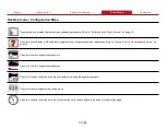
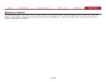
Enabling and Disabling a DLA—Screen Views

< SOLUTION

SYSTEM >

REAR DRIVER / DECK GUN 5"

306

10201

30

1000

REAR PASSENGER 2~1/2”

603

20102

11.3

375

REAR PASSENGER

2~1/2”

REAR DRIVER /

DECK GUN 5"

DRIVER 6”

151.1

5038

37.5

1250

DRIVER 6”

FRONT / REAR CROSSLAY 1~3/4”

136.9

4563

3

100

FRONT / REAR

CROSSLAY 1~3/4”

PASSENGER 6"

89.2

2972

37.5

1250

PASSENGER 6"

#1 / #2 DRIVER 2~1/2”

524.7

17491

11.3

375

#1 / #2 DRIVER

2~1/2”

DECK GUN 8”

298.5

9950

75

2500

DECK GUN 8”

#1 / #2

PASSENGER 2~1/2”

#1 / #2 PASSENGER 2~1/2”

111.2

3708

11.3

375

2

1

< SYSTEM

GAUGE >

REAR PASSENGER

2~1/2”

DRIVER 6”

FRONT / REAR

CROSSLAY 1~3/4”

PASSENGER 6"

#1 / #2 DRIVER

2~1/2”

DECK GUN 8”

#1 / #2 PASSENGER 2.5”

GAL

GAL

CONCENTRATE 

PRESSURE

RELIEF

750

111.2

3.0

3708

GPM

375

11.3

112.0 

#1 / #2

PASSENGER 2~1/2”

CONCENTRATE ON 

4

3

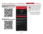
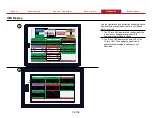
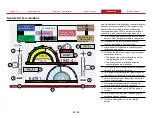
Use the illustrations and instructions to enable and 

disable a discharge. A discharge consists of a DLA 

and dedicated waterline from the fire pump. 

Enabling a discharge on the screen enables the 

associated DLA that is then activated by flowing 

water through the dedicated waterline. After start-

up, the system opens to the DLA Gauge screen.

1 The gauge screen displays the available 

discharges, their status, and their statistics 

since panel power-up. Enable and disable any 

discharge by doing the following:

• 

Long-press any 

DLA 

button to enable that 

DLA. The button appearance changes to 

indicate that the DLA is enabled. A border 

appears around the button, and the DLA 

name animates when the DLA is active.

• 

Long-pressing an enabled DLA disables that 

DLA, and reverts the button to its original 

appearance.

• 

Short-press any 

DLA 

button from any screen 

to navigate to the solution screen for that 

DLA.

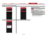
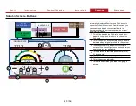
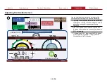
2 The DLA information box updates to show the 

status, and the associated statistics update 

when it is active.

3 The concentrate source icon animates on the 

solution screen for any DLA that is enabled.

4 Another indication that the DLA is enabled is 

that the 

Concentrate On/Off

 is in the 

On


state. Press the 

Concentrate On/Off 

button


to disable that DLA.

Содержание AQUIS ULTRAFLOW

Страница 1: ...AQUIS ULTRAFLOW Tellurus HMI Installation and Operation Form Number F 2925 Issue Date Jun 29 2021 Waterous Company 125 Hardman Avenue South South Saint Paul MN 55075 651 450 5000 www waterousco com...

Страница 2: ......

Страница 3: ...guring the System 25 Desktop Icons 27 Desktop Icons Operation Menu 28 Desktop Icons Customer Service Menu 29 Desktop Icons Configuration Menu 30 Desktop Icons Maintenance Menu 31 Using the Live Troubl...

Страница 4: ...e equipment if you are not familiar with the tools and skills needed to safely perform the required procedures proper installation is the responsibility of the purchaser Do not operate the equipment w...

Страница 5: ...h the basic knowledge of operating similar equipment The information in this document is subject to change without notice This document is divided into the following sections Safety This section descr...

Страница 6: ...6 56 Safety Introduction Product Overview Installation Operation Maintenance AQUIS ULTRAFLOW Industrial Foam Proportioner System 1 4 5 3 2 9 9 8 7 6...

Страница 7: ...nal options required in your application Various cables these provide communication and power to system components 2 Discharge line assembly This manages the concentrate injected into the solution cap...

Страница 8: ...n or supply foam concentrate for the system The components in this subsystem include Concentrate supply tank this contains the on board foam concentrate supply Tank full sensor this indicates a tank f...

Страница 9: ...s connects to and controls the concentrate control valve flowmeters Split CANbus cable this connects the node controllers to one another and the control box Concentrate control valve this controls the...

Страница 10: ...ents A comprehensive application of the AQUIS ULTRAFLOW system consists of multiple subsystems that include up to 19 DLAs to perform various functions an on board and auxiliary concentrate supply equi...

Страница 11: ...em The HMI display interfaces with the control system and provides the operator information and control over system operation The components in this subsystem include 8 inch or 15 inch Tellurus displa...

Страница 12: ...ety Introduction Product Overview Installation Operation Maintenance 15 Inch Tellurus HMI The Tellurus display or HMI displays current operations and provides operator control over the system 2 1 3 4...

Страница 13: ...3 Mounting knob This secures the HMI to the apparatus 4 Mounting bracket This secures the HMI to the apparatus 5 RJ45 connector This connects to a secondary HMI or truck Ethernet network 6 WiFi connec...

Страница 14: ...ety Introduction Product Overview Installation Operation Maintenance 8 Inch Tellurus HMI The Tellurus display or HMI displays current operations and provides operator control over the system 2 1 3 4 9...

Страница 15: ...Mounting knob This secures the HMI to the apparatus 4 Mounting bracket This secures the HMI to the apparatus 5 RJ45 connector This connects to a secondary HMI or truck Ethernet network 6 WiFi connect...

Страница 16: ...16 56 Safety Introduction Product Overview Installation Operation Maintenance WiFi and GPS Antenna The antenna receives WiFi and GPS signals 1 2 3 4...

Страница 17: ...Antenna Feature Feature Description Description 1 Antenna This receives the WiFi and GPS signals 2 Nut cover This secures the antenna to the apparatus 3 GPS connector This connects the GPS connector...

Страница 18: ...cts to the Tellurus display Deutsch DT06 12SB 2 Deutsch connector This connects to apparatus power DT04 6P E003 3 Deutsch connector This connects to the Y splitter receptacle 4 Y splitter receptacle T...

Страница 19: ...1 2 3 Feature Feature Description Description 1 M12 connector This connects to the Tellurus HMI CANbus connector on the control box or an extension cable connected to the control box 2 Cable This is a...

Страница 20: ...and gather all the necessary tools before you begin the installation Make sure that you remove any shipping plugs or caps before installing the component Make sure that you bring all fluids to operat...

Страница 21: ...der the cable and hose routing Consider accessibility during operation and maintenance Install instruction plates near their applicable operator panels Refer to the dimensional drawings for cutout and...

Страница 22: ...22 56 Safety Introduction Product Overview Installation Operation HMI Cables and Connections 8 4 6 5 1 2 3 7...

Страница 23: ...and GPS signals 3 HMI cable This connect the HMI to power and to the HMI M12 cable 4 HMI M12 cable This connect the HMI cable to the control box 5 Control box This connects to various components in t...

Страница 24: ...nect the compatible connector on the HMI cable assembly to the display extension cable connector 3 Connect compatible connector on the display extension cable to the control box the HMI CANbus connect...

Страница 25: ...iguration and the other is the user level configuration The installer level configuration defines permanent aspects of the system number of DLAs flowmeter calibration units of measure along with other...

Страница 26: ...o upload a new or restore to a previous configuration To transfer configuration files you will need the following A USB hub to connect the HMI to the keyboard and USB drive A USB keyboard to navigate...

Страница 27: ...es Report All Run Time System Help Total Con Used Total Water Customer Service Customer Service Customer Service Customer Service Remote Connection System Info Configurations Configurations Calibrate...

Страница 28: ...umber of power cycles Press this icon to navigate to the totals menu From there you can review and reset the values for the total run time total concentrate used and total water used Press this icon t...

Страница 29: ...icon to initiate a troubleshooting ticket with Customer Services Press this icon to display a QR code to navigate to the customer service help documentation Press the icon to open a live troubleshoot...

Страница 30: ...code that navigates to the configuration help documentation Refer to Using the Live Troubleshooting App on page 34 Press this icon to change discharge colors Press this icon to change discharge names...

Страница 31: ...t various system components Press this icon to navigate to the flowmeter calibration Use the available options to calibrate the desired flowmeter Press this icon to prepare a summary system log report...

Страница 32: ...e troubleshooting session by using your phone as a WiFi hotspot Once connected information about your system is available to the Support Department to assist you in troubleshooting your system Note If...

Страница 33: ...initiate a remote session do the following Activate the hotspot feature on your mobile phone Go to the setting menu to capture the hotspot name and password you will use this information later 2 Conne...

Страница 34: ...instructions to open a live troubleshooting session or to access additional system documentation 5 Locate your hotspot in the list of available hotspots 6 Enter the hotspot passphrase into the connect...

Страница 35: ...n initiates the touch screen calibration procedure Calibrate the touchscreen any time the finger press activation is misaligned or after any operating system firmware update To calibrate the touchscre...

Страница 36: ...desired setting or adjustment Tellurus Command Interface Tellurus Command Interface Enter any of the following commands at the prompt to perform HMI functions help help Show command interface help ex...

Страница 37: ...the pump panel 1 This is the first start up screen This screen indicates that the display is receiving power and the boot sequence has initiated 2 This screen displays as the Tellurus begins to commu...

Страница 38: ...3 375 1 2 PASSENGER 2 1 2 1 SOLUTION SYSTEM REAR DRIVER DECK GUN 5 306 10201 30 1000 REAR PASSENGER 2 1 2 603 20102 11 3 375 DRIVER 6 151 1 5038 37 5 1250 FRONT REAR CROSSLAY 1 3 4 136 9 4563 3 100 PA...

Страница 39: ...ystem opens in the DLA gauge screen after start up This screen displays the available DLAs their status and basic statistics Keep in mind the appearance of the DLA gauge screen the number of DLAs thei...

Страница 40: ...ution screen From this screen you can enable and disable concentrate flow to the discharge adjust the percent and view the current and total flow values 1 This button displays the DLA state enabled or...

Страница 41: ...flow to the discharge adjust the concentrate percent and view the current and total flow values 1 This is the name of the selected DLA 2 This is the total amount of concentrate dispensed from the sele...

Страница 42: ...m 2 This enables the refill process when the concentrate source is set to auxiliary 3 Press and hold this button to manually prime the concentrate pump 4 This enables the relay or transfer process and...

Страница 43: ...n the illustration 1 This graphically and numerically shows the current concentrate flow rate for all active DLAs as well as the concentrate line pressure 2 This graphically and numerically shows the...

Страница 44: ...dicated waterline from the fire pump Enabling a discharge on the screen enables the associated DLA that is then activated by flowing water through the dedicated waterline After start up the system ope...

Страница 45: ...t best conveys the topic 1 The fire pump flows water into the discharge 2 The enabled DLA measures the water flow in the discharge 3 The concentrate pump activates 4 The magnetic flowmeter measures th...

Страница 46: ...2 PASSENGER 2 1 2 CONCENTRATE ON 2 3 1 Use the illustration and instructions to adjust the concentrate percentage for a specific discharge 1 Typically the solution parameters are set during calibrati...

Страница 47: ...ations and instructions to understand how the concentrate source is determined by the system The system installer provides and defines a signal to the system as well as a method for switching between...

Страница 48: ...this illustration only focuses on the specific activity in the system that best conveys the topic 1 When set to auxiliary supply mode a valve is used to change the concentrate source from the on board...

Страница 49: ...ASSENGER 2 5 1 2 DRIVER 2 1 2 1 2 PASSENGER 2 1 2 5 4 Use the illustrations and instructions to refill the on board concentrate supply tank from an external source This is useful when manually refilli...

Страница 50: ...e refilling the tank Note For instructional purposes this illustration only focuses on the specific activity in the system that best conveys the topic 1 The system sources concentrate from the auxilia...

Страница 51: ...me the system by pressing the prime button until the system is primed Note For instructional purposes the system illustration only focuses on the specific activity in the system that best conveys the...

Страница 52: ...instructions to transfer concentrate to another location If included in your application you can use the transfer line to move the concentrate from the on board tank to another location You can opera...

Страница 53: ...and instructions to relay concentrate to another location If included in your application you can use the transfer DLA to move the concentrate from an external source to another location You can opera...

Страница 54: ...ce is required for the control system However it is recommended that you periodically inspect the system to reveal excessive debris buildup worn components or any developing leaks Consider environment...

Страница 55: ...Notes 55 56...

Страница 56: ...Waterous Company 125 Hardman Avenue South South Saint Paul MN 55075 651 450 5000 www waterousco com...

Отзывы: