16
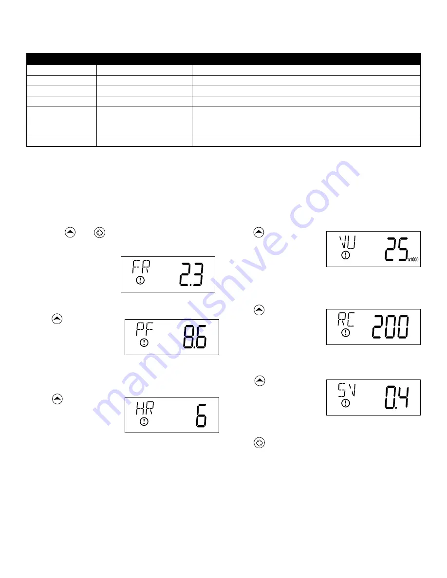
5. Press . Use this display
to view the Volume
Used since the last
regeneration cycle. This
option setting is identified
by “VU” in the upper
left hand corner of the
screen.
6. Press . Use this display
to view the Reserve
Capacity. This option
setting is identified by
“RC” in the upper left
hand corner of the
screen.
7. Press . Use this display
to view the Software
Version. This option setting
is identified by “SV” in the
upper left hand corner of
the screen.
8. Press to end Diagnostic Programming Mode.
Diagnostic Programming Mode
Diagnostic Programming Mode Steps
1. Press the and buttons for five seconds while in
service.
2. Use this display to view
the current Flow Rate.
This option setting is
identified by “FR” in the
upper left hand corner
of the screen.
3. Press . Use this display
to view the Peak Flow
Rate since the last
regeneration cycle. This
option setting is identified
by “PF” in the upper
left hand corner of the
screen.
4. Press . Use this display
to view the Hours in
Service since the last
regeneration cycle. This
option setting is identified
by “HR” in the upper
left hand corner of the
screen.
Diagnostic Programming Mode Options
Abbreviation
Parameter
Description
FR
Flow Rate
Displays the current outlet flow rate
PF
Peak Flow Rate
Displays the highest flow rate measured since the last regeneration
HR
Hours in Service
Displays the total hours that the unit has been in service
VU
Volume Used
Displays the total volume of water treated by the unit
RC
Reserve Capacity
Displays the system’s reserve capacity calculated from the system
capacity, feed water hardness, and safety factor
SV
Software Version
Displays the software version installed on the controller
NOTES:
Some items may not be shown depending on timer configuration.
The timer will exit Diagnostic Mode after 60 seconds if no buttons are pressed.
Press the Extra Cycle button to exit Diagnostic Mode at any time.


