15.2.1.1
Resin chocks
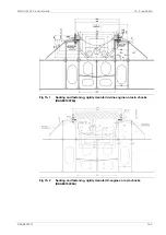
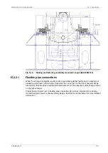
The recommended dimensions of the resin chocks are 600 x 180 mm. The total surface
pressure on the resin must not exceed the maximum value, which is determined by the type
of resin and the requirements of the classification society.
It is recommended to select a resin type that is approved by the relevant classification society
for a total surface pressure of 5 N/mm
2
. (A typical conservative value is P
tot
3.5 N/mm
2
).
During normal conditions, the support face of the engine feet has a maximum temperature of
about 75°C, which should be considered when selecting the type of resin.
The bolts must be made as tensile bolts with a reduced shank diameter to ensure a sufficient
elongation since the bolt force is limited by the permissible surface pressure on the resin. For
a given bolt diameter the permissible bolt tension is limited either by the strength of the bolt
material (max. stress 80% of the yield strength), or by the maximum permissible surface
pressure on the resin.
Locking of the upper nuts is required when the total surface pressure on the resin chocks is
below 4 MPa with the recommended chock dimensions. The lower nuts should always be
locked regardless of the bolt tension.
15.2.1.2
Steel chocks
The top plates of the engine girders are normally inclined outwards with regard to the centre
line of the engine. The inclination of the supporting surface should be 1/100. The seating top
plate should be designed so that the wedge-type steel chocks can easily be fitted into their
positions. The wedge-type chocks also have an inclination of 1/100 to match the inclination
of the seating. If the top plate of the engine girder is fully horizontal, a chock is welded to each
point of support. The chocks should be welded around the periphery as well as through holes
drilled for this purpose at regular intervals to avoid possible relative movement in the surface
layer. The welded chocks are then face-milled to an inclination of 1/100. The surfaces of the
welded chocks should be large enough to fully cover the wedge-type chocks.
The supporting surface of the seating top plate should be machined so that a bearing surface
of at least 75% is obtained. The chock should be fitted so that they are approximately equally
inserted under the engine on both sides.
The chocks should always cover two bolts, except the chock closest to the flywheel, which
accommodates only one bolt. Steel is preferred, but cast iron chocks are also accepted.
Holes are to be drilled and reamed to the correct tolerance for the fitted bolts after the coupling
alignment has been checked and the chocks have been lightly knocked into position.
15.2.1.3
Steel chocks with adjustable height
As an alternative to resin chocks or conventional steel chocks it is also permitted to install the
engine on adjustable steel chocks. The chock height is adjustable between 45 mm and 65
mm for the approved type of chock. There must be a chock of adequate size at the position
of each holding down bolt.
15-2
DAAB605814
Wärtsilä 46F Product Guide
15. Foundation
Содержание 46F Series
Страница 1: ...Wärtsilä 46F PRODUCT GUIDE ...
Страница 4: ...This page intentionally left blank ...
Страница 8: ...This page intentionally left blank ...
Страница 18: ...This page intentionally left blank ...
Страница 46: ...Fig 4 3 Cross section of the V engine 4 6 DAAB605814 Wärtsilä 46F Product Guide 4 Description of the Engine ...
Страница 86: ...This page intentionally left blank ...
Страница 104: ...This page intentionally left blank ...
Страница 154: ...This page intentionally left blank ...
Страница 162: ...This page intentionally left blank ...
Страница 170: ...This page intentionally left blank ...
Страница 176: ...This page intentionally left blank ...
Страница 194: ...This page intentionally left blank ...
Страница 200: ...This page intentionally left blank ...
Страница 202: ...This page intentionally left blank ...
Страница 207: ...Fig 21 7 List of symbols DAAF406507 7 DAAB605814 21 5 21 ANNEX Wärtsilä 46F Product Guide ...

