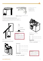
2.1.14. Installation at Partially Protected Outsides
Installation Instructions:
This combi can be installed in partially
protected outsides Partially protected area means the place where the
boiler will not be directly exposed to atmospheric factors and weather
conditions (rain, snow, etc.)
Frost Protection:
The boiler is equipped with a system that prevents
frost by automatically activating the pump and boiler when the internal
water is lower than 5°C.
Frost protection function only depends on below given conditions:
-If the combi is correctly connected to gas and electrical sources;
-If the combi is supplied from gas and electricity sources in a fixed way;
-If the Combi is not in failure situation due to lack of ignition;
-If radiator installation pressure is full and radiator valves are open;
The boiler is protected against frost up to -5°C ambient temperature.
Lowest Temperature -5°C.
In case the boiler is installed in an
environment with a temperature lower than -5°C, and gas supply is
interrupted or passed into failure due to failing to make ignition, Frost
Prevention System shall not be activated and frost/failure shall occur in
the device. Following instructions should be followed for preventing the
risk of frost:
- Heating circuit, into antifreeze (special heating devices) a good brand of
antifreeze manufacturer's instructions are followed carefully so as it deems
necessary for the rate and the minimum temperature is desired to be stored
in the heater frost protection with the matter.
Materials used for manufacturing the combi are resistant against glycol and
propylene based anti-frost liquids. Follow warnings of supplier company
regarding their technical service life and possible disposals.
Frost / icing protection of the combi is guaranteed only under these
conditions:
Any damages caused by noncompliance to the terms specified above
and power loss are excluded from warranty.
If the boiler is installed in places where temperature drops below
0°C (both for hot domestic water and heating purposes), pipes of the
heating system and domestic water installation must be insulated.
2.1.15. Electrical Connections
Ensure electrical safety of boiler by connecting to an effective earthing
installation that follows safety instructions in force.
Earthing shall not be performed through the neutral line on the socket
in places without earthing! It is dangerous and unacceptable to use gas
and water connection pipes for earthing.
WARMHAUS A.Ş. cannot be held responsible for any damage or
loss to individuals or property arising from failing to provide earth
connection of the boiler and not being fitted by a competent
Electrician or registered individual in accordance with directives and
standards in force in the country where the boiler is installed.
Also, ensure that the electricity installation complies with the maximum
power to be supplied as indicated in technical specifications label.
boiler shall be energized with "X" type socketless special power supply
cables. "Warmhaus boiler has an IPX5D protection level. Power supply cable
should be connected to 230 V +%10; -%15 50Hz grid with L-N poles and
relying on the earth connection, high voltage category 3rd class multiple
poled disconnected should be envisaged on the same grid. Contact our
Authorized Warmhaus Service for replacement of the cable.
The power supply cable must follow the specified route. In
case of replacing fuses on the board, use 2A or 3,15A quick
type fuse.
In order to feed the device from the mains, adapter, multiple sockets
and extension cables are not permitted.
2.1.16. Optional Controls: Room Thermostat, Outside Temperature
Sensor and Others
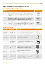
Room thermostat, External Weather Temperature Sensor, etc. control
devices must be connected to Warmhaus boiler devices by the
authorized service personnel; In case connections are performed by
unauthorized persons, boiler warranty shall be void.
Room thermostat, outside Temperature Sensor, etc. control
devices are provided as optional accessories for Warmhaus
boiler devices and they must be Warmhaus approved.
Please follow instructions of use for placement of outside Temperature
Sensor.
This sensor can be directly connected to electrical installation of
the boiler, and it automatically reduces the maximum return water
temperature in the installation when outside temperature rises for
enabling functioning according to outside temperature changes sent
to radiator installation outside Temperature Sensor is activated when
connected as independent from the used room thermostat typology
and functions together with room thermostats. The relation between
installation input temperature and outside temperature is defined
according to curves in the diagram from position of the button located
on the panel of boiler (or on the control panel if connected to boiler
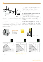
(Figure 39).
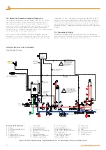
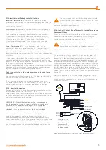
Electrical connection of the Outsides Weather Temperature Sensor
shall be made to the terminals to which the White & White cables
of the Aux cable connected to the electronic card of the boiler are
connected (Figure 27).
24V AC
G S M
OT
THERMOSTAT BRIDGE
OPENTHERM CONTACT
OUTDOOR TEMPERATURE SENSOR
WHITE
ORANGE
TO PCB
THERMINAL
OPEN THERM
CONNECTION
ORANGE
WHITE
A
PCB
PCB
PCB
BLUE
BROWN
DHW TANK PROBE
PCB
PCB (A8)
BLACK
3-WAY VALVE
CH OPEN
PHASE (L1)
DHW OPEN
PHASE (L2)
NEUTRAL (N)
OUTDOOR
TEMPERATURE
SENSOR
WHITE
ORANGE
GREEN
GREEN
BLUE
BROWN
B
Attention: During
ON-OFF and
Room Thermostat
connections, B
Bridge cable shall
be disconnected.
Şekil 27
Kazan oda termostatı ve dış hava sıcaklık sensörü bağlantıları.
15
Содержание VIWA 50
Страница 1: ...WALL MOUNTED CONDENSING BOILERS INSTALLATION USER MANUAL VIWA50 VIWA65...
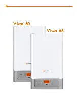
Страница 2: ...Viwa 50 Viwa 65...
Страница 35: ...50 61 Viwa 50 65 58 Viwa 65 35 35...


