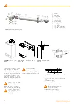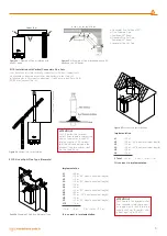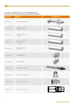
a- Horizontal Flue Set Bend (90°)
b- Flue Extension Pipe
c- Additional 45° Bend
d- Standard Flue Set Pipe-
Additional 45° Bend
f- Horizontal Flue Set Pipe
Figure 23
III. Example of flue installation with one 90°
bend and two 45° bends
d
f
e
b c
a
a + b + c + d + e + f < 9 m.
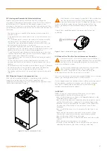
2.1.12. Installation with Vertical Concentric Flue Sets
Your boiler can also be vertically connected to flat and sloping roofs
via available connection accessories depending on the status of
installation place. For direct connections, it shall not exceed 11m with (Ø
80/125 mm) vertical flue set.
2.1.13. Use of Split Flue Type (Hermetic)
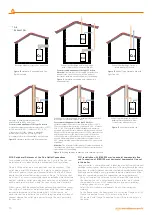
Figure 25
Vertical flue set installation
Şekil 26
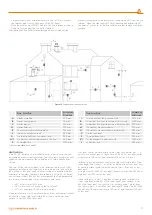
Example of Split Flue (Hermetic) Type
Implementation
L1
=0.3 m.
L2
=0.5 m.
(45° bend equivalent length)
L3
=2.0 m.
L4
=0.5 m. (45° bend equivalent length)
L5
=1.0 m.
L6
=2.0 m.
L Total
=6.3 m. 6.3 m. < Lmax = 11 m.
It is correct in implementation.
Implementation
L1
=0.5 m.
L2
=1.0 m.
(90° bend equivalent length)
L3
=1.5 m.
L4
=1.0 m. (90° bend equivalent length)
L5
=1.5 m.
L6
=0.5 m.
L7
=1.0 m.
(90° bend equivalent length)
L8
=0.5 m.
L9
=0.5 m.
(45° bend equivalent length)
L10
=1.5 m.
L11
=1.0 m. (90° bend equivalent length)
L12
=1.5 m.
L Total =12 m.
12 m. < Lmax = 30 m.
It is correct in implementation.
Figure 22
I. Example of flue installation with
one 90° bend
a
d
b
Lmax = 10 m
Figure 24
Vertical flue set installation
Ø
80
/1
25
mm
= L
ma
x. =
11 m
ATTENTION!
For C3 boilers the terminal
outlets from separete combustion
and air supply circuits shall fit
inside a square of 50 cm and
that the distance between the
planes of the two orifices shall
be less than 50 cm.
ATTENTION!
For C1 boilers the terminal outlet
from separete combustion and
air supply circuits shall fit inside a
square of 50 cm for boilers with
a heat input up to 70 kW
13
Содержание VIWA 50
Страница 1: ...WALL MOUNTED CONDENSING BOILERS INSTALLATION USER MANUAL VIWA50 VIWA65...
Страница 2: ...Viwa 50 Viwa 65...
Страница 35: ...50 61 Viwa 50 65 58 Viwa 65 35 35...


