Use
45
EN
Switching on /off
Connecting the power
The welder is designed for use with single phase
alternating current 230 V AC / 50 Hz and is
double-insulated. Make certain that the rated
voltage indicated on the welder's rating plate
matches the local mains voltage.
If the work area is not close to the mains outlet,
use an extension cable with sufficient conductor
diameter (min. 1,5 mm)
2
).
The extension cable used should be as short as
possible. Mains circuit: The mains circuit must
be equipped with a trip switch or fuse with a
maximum rating of 16 A (slow blow).
The welder should only be connected to a
properly installed mains socket. Repairs may
only be carried out by a qualified electrician.
The welder is equipped with an automatic
safety device (self-resetting thermal overload
protection device) which protects the device
from thermal overload. The protective device
interrupts the circuit and switches on the yellow
overload indicator.
• Allow the welder to cool down for about 15
minutes if the overload protection is tripped.
When the yellow light 8 goes out, the
welder can be used again.
• Prepare the welder for the required work (see
"Electrode welding").
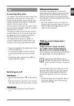
• Ensure that the welder is switched off: The
operating switch 2 has to be in position
"o".
• Connect the mains cable with plug 3 to a
suitable electrical socket.
The required welding current depends on the
diameter of the electrode used, the strength
of the material being welded and the weld
penetration required or the size of the weld
pool.
• With the welding current regulator 6 you
can set the welding current continuously
from 20 to 120 Amps.
Use
Switching on:
• Press the operating switch 2 to ON position
"I".
• When the welder is switched on, the indicator
7 glows and the cooling fan starts running.
Switching off:
• Press the operating switch to OFF position
"O".
Thermal overload protection:
Welding current adjustment
WARNING!
Danger of burns! Always use pliers
or a similar tool to remove used, hot
electrodes or hot, welded workpieces.
The workpieces and electrodes become hot
during welding. You could get burns.
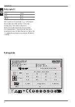
Depending on the welding current
adjusted, the duty cycle X of the device
varies (see table in chapter "Duty cycle
X").
Содержание WWS-120B2-K01
Страница 3: ...1 2 3 4 5 6 7 8...
Страница 4: ...9 10 11 12 13 14 15 16 17 18 19 20 21 22 23 24 25...
Страница 5: ...A C B 11 16 22 21 20 16 24 19 23 18 17 24 25 10 15 4 5 13 12 14 E F D...
Страница 32: ...32...
Страница 54: ...Exploded view 54 EN Exploded view 6 7 8 9 14 13 10 11 15 12 4 16 19 20 21 22 23 24 29 28 27 26 25 1 18 5 2 17...
Страница 80: ...Dessin clat 80 FR Dessin clat 6 7 8 9 14 13 10 11 15 12 4 16 19 20 21 22 23 24 29 28 27 26 25 1 18 5 2 17...
Страница 104: ...V kres d l 104 CZ V kres d l 6 7 8 9 14 13 10 11 15 12 4 16 19 20 21 22 23 24 29 28 27 26 25 1 18 5 2 17...
Страница 128: ...Razstavljena risba 128 SI Razstavljena risba 6 7 8 9 14 13 10 11 15 12 4 16 19 20 21 22 23 24 29 28 27 26 25 1 18 5 2 17...
Страница 131: ...131...


