background image

BXTR6438
Trailer Wood Chipper

Operating Instructions

43

5.11 Unplugging the Chipper

The wood chipper is designed to handle a wide range of material 
sizes without any problem. However, in the event material 
gets lodged in the chipper, follow this procedure to clear the 
blockage. 

1. 

Before shutting the engine off, reverse the feed rollers to 

remove the material from the feed hopper. 

2.  Place the machine in a Safe Condition before proceeding 

further.

 See 

page 8

.

3. 

Clear all the material out of the feed hopper. Make sure 

nothing is jammed or wedged between the feed rollers 

and the rotor. If material is jammed in this area, proceed to 

Step 7.

If the chipper is still plugged or the engine has shut down, the 
jammed material must be removed by hand.

 CAUTION!

Be aware of the risk of injury. Rotor continues to 

turn for a few revolutions after engine is stopped. 

Wait for all parts to stop moving before opening 

any machine access.

W092

 CAUTION!

The chipper blades are very sharp. Use caution 

when reaching into the rotor compartment to 

clear stuck material.

W026

4. 

Remove the rotor housing flange bolt and open the housing. 
Clear out any jammed material inside. 

5. 

Pull any remaining material out of the feed hopper and 
discharge hood.

6. 

Use a stick to poke any material loose jammed into the 
discharge hood. Be sure all the material is cleared out, and 
nothing is jammed or wedged between the input opening 
and the rotor.

7. 

Check that everyone is clear of machine before restarting 
engine.

8. 

Start the engine and resume working.

 WARNING!

Never operate a machine with any guards 

or shields removed. The machine is shown 

here with guards and/or shields removed for 

illustrative purposes only.

W001

01578

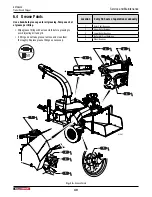
Fig.  35 – 

Open Upper rotor Housing to clear Jam

Содержание 2E9US111XNS091454

Страница 1: ...OPERATOR S MANUAL Trailer Wood Chipper BXTR6438 BXTR6438B Document Number Z97157_En Rev Jun 2022 TECHNOLOGY Serialnumber2E9US111XNS091454 to2E9US1111NS091468...

Страница 2: ...fore Startup 34 5 2 Pre start Checks 34 5 3 Machine Break In 35 5 4 Engine Oil Level Check 35 5 5 Fuel Level Check 36 5 6 Hydraulic Oil Level Check 37 5 7 Machine Set up 38 5 8 Starting Procedure 39 5...

Страница 3: ...hat anyone using or maintaining the machine reads and understands the Safety Operation Maintenance information contained within this Operator s Manual Keep this manual handy for frequent reference and...

Страница 4: ...Model Serial Number Delivery date I have thoroughly instructed the buyer on the equipment care adjustments safe operation and applicable warranty policy and reviewed the manuals Dealer Address City St...

Страница 5: ...VIN NLV MODEL Manufactured by Wallenstein Equipment Inc 7201 Line 86 Wallenstein ON N0B2S0 Canada TYPE OF VEHICLE TYPE DE VEHICLE TRA REM GAWR PNBE KG GVWR PNBV KG DIMENSION RIM JANTE E R I T PNEU COL...

Страница 6: ...ks Product Decals indicate machine model and serial number and other important information VIN NLV MODEL Manufactured by Wallenstein Equipment Inc 7201 Line 86 Wallenstein ON N0B2S0 Canada TYPE OF VEH...

Страница 7: ...alert against unsafe practices IMPORTANT To avoid confusing equipment protection with personal safety messages a signal word IMPORTANT indicates a situation that if not avoided could result in damage...

Страница 8: ...ous injury or death It is the owner s responsibility to make sure to the operator has familiarity and understanding of the machine Do not modify disable or change the roller feed safety control bar in...

Страница 9: ...od chips can cause injuries Keep children away Never place any part of your body where it would be in danger if machine movement should occur during assembly installation operation maintenance repairi...

Страница 10: ...battery electrolyte External Contact Flush immediately with water Eye Contact Flush with water for 15 minutes Get prompt medical attention Clean up any spilled electrolyte immediately Avoid contact w...

Страница 11: ...plug wire removed DO NOT crank engine with spark plug removed If engine is flooded crank until engine starts DO NOT strike flywheel with a hard object or metal tool as this may cause flywheel to shat...

Страница 12: ...sign off sheet provided below can be used Make periodic reviews of Safety and Operation a standard practice for all operators Review again at the startup of every season The design and manufacture of...

Страница 13: ...safety alert the potential hazard and the bottom or right hand panel shows the message how to avoid the hazard Hazard How to avoid the hazard Practicing good safety means becoming familiar with safety...

Страница 14: ...350 12 1 Warning Risk of high pressure hydraulic fluid piercing exposed skin Do not check for leaks with hand or fingers Serious injury can result 2 Warning Risk of explosion Do not refuel the machine...

Страница 15: ...t put material larger than 7 18 cm diameter into the chipper Attempting to chip anything larger could stall the engine damage the machine or cause personal injury 6 Caution Risk of serious injury or d...

Страница 16: ...at have safety signs on them new signs must be applied Safety signs must always be replaced if they become damaged are removed or become illegible Safety signs are available from your authorized deale...

Страница 17: ...g or repairing See page 8 3 2 Job Site Familiarization It is the responsibility of the operator to be thoroughly familiar with the work site prior to starting Prevent the chance or possibility of prob...

Страница 18: ...8 1 Fuel tank 2 ST205 75R14 LRC Radial Tires 3 Electric Brakes Option 4 Kohler CH980 Engine 5 P3 Electronic Control System Display 6 Drive Belt 7 Discharge Chute 8 Hood Deflector 9 Upper Housing Rotat...

Страница 19: ...Assembly Lift Handle 20 Stop Tail Turn Signal Light 21 Hydraulic Motor 22 Ledger Blade 23 Twig Breaker 24 Upper Rotor Housing 25 Operators Manual 26 Rotor 27 Rotor Blade 28 Bridge Guard 29 Hydraulic P...

Страница 20: ...ated switch controls the electric power to the engine The switch has three positions OFF RUN and START O FF R U N S T A R T 01557 Fig 5 Ignition Switch O OF FF F OFF Turn key fully counterclockwise to...

Страница 21: ...the choke when starting a cold engine Slide it to the left gradually to open the choke as the engine warms Always slide the choke fully to the left when operating the machine 4 1 3 Throttle This lever...

Страница 22: ...the latch handle and lock the chute into position at the next nearest lock point 01560 Fig 8 Adjusting Discharge Chute 4 3 Hood Deflector The discharge chute is equipped with a hood deflector on the e...

Страница 23: ...e of the feed table indicate feed control bar operation The control bar can be moved freely between Forward and Reverse 00125 Fig 10 Feed Roller Control Bar Positions RH side shown 4 4 1 STOP Position...

Страница 24: ...the forward feed This is the normal operating position The control bar stays in this position until moved 01564 Fig 13 Forward Feed 4 4 3 Reverse Feed Rollers Place the feed roller control bar in the...

Страница 25: ...ws to below the minimum rotor speed setting the P3 PULSE auto reverses the feed rollers to pull material away from the rotor When the rotor speed returns to the operating rpm the P3 PULSE returns the...

Страница 26: ...ready to operate 01830 F R N Red Solid Rotor jam Clear the rotor jam to continue operation 01830 R N Red Fast flash Upper rotor housing is open Close the upper rotor housing to continue operation Feed...

Страница 27: ...y above the soft key navigation buttons They indicate the current selection options and are only shown when a selection is available Settings Home Up arrow Down arrow Select enter Cancel 3 Soft Key Na...

Страница 28: ...RD green arrows feed rollers are going forward Material in the rollers is pushed into the rotor LOW RPM LOW RPM green arrows with the feed control bar in Forward the feed rollers are not moving becaus...

Страница 29: ...current feed settings OEM SETTINGS Only authorized Wallenstein Equipment personnel are permitted to access the original equipment manufacturer OEM settings see page 32 Open a screen 1 Use the soft key...

Страница 30: ...Speed FEED START SPEED 0000 Sets the rpm point where the feed rollers start to operate Min Rotor rpm MIN ROTOR RPM 0000 Sets the low rpm point where the feed rollers auto reverse If the rotor speed s...

Страница 31: ...ration you can observe all the machine parameters on this screen The Diagnostics screen displays the following information ENGINE RPM for example 3600 Machine model for example BXTR5224 Current state...

Страница 32: ...DEFAULTS DIAGNOSTICS OEM SETTINGS OEM Settings IMPORTANT Only authorized Wallenstein Equipment personnel are permitted to access the OEM settings If an unauthorized person accesses the OEM settings i...

Страница 33: ...up 01572 Fig 23 Trailer Hook up 6 Cross safety chains under the trailer tongue and attach securely to the tow vehicle 7 Connect the wire harness plug to the tow vehicle Make sure there is provide sla...

Страница 34: ...see page 20 9 Survey the work site and place the chipper in a clear level work area 10 Set up the machine correctly See Machine Setup page 38 5 2 Pre start Checks Check the following each time the woo...

Страница 35: ...hardware After 8 hours of operation 12 Repeat all previous steps 13 Check wheel bolt torque after 20 25 mi 32 40 km Regularly check weekly 14 Perform all the checks in the Pre start checks See page 3...

Страница 36: ...e restarting engine Do not overfill the fuel tank If fuel is spilled wipe it away carefully and wait until the fuel has dried before starting the engine Do not refuel the machine while smoking or when...

Страница 37: ...in the sight glass Damage to the pump and other components can occur Do not overfill the tank past the sight glass window IMPORTANT Hydraulic oil quality should be inspected every 50 hours If the oil...

Страница 38: ...jects The machine can expel wood chips fast enough to cause eye cut and impact injuries and or property damage W024 Follow this procedure to prepare and set up the machine at the work site 1 Use the t...

Страница 39: ...arting attempt pause briefly at RUN to power up system electronics 7 Operate at low idle for a few minutes to allow the engine to warm 8 Gradually open the choke 9 Turn the discharge head to its desir...

Страница 40: ...e condition and then clear the jam W004 IMPORTANT Do not put metal objects bottles cans rocks glass or other foreign material into wood chipper If such items happen to get into the chipper stop machin...

Страница 41: ...ced in the Forward feed position NOTE Engine throttle must be at MAX and rotor at full speed for feed rollers to function in Forward Feed rollers function in Reverse even at engine idle so material ca...

Страница 42: ...djust as required 4 Torque all fasteners and hardware 5 Check condition of rotor bearings 6 Check the condition and clearance of the twig breaker rotor and ledger blades Adjust as required 7 Check for...

Страница 43: ...he risk of injury Rotor continues to turn for a few revolutions after engine is stopped Wait for all parts to stop moving before opening any machine access W092 CAUTION The chipper blades are very sha...

Страница 44: ...the rotor housing while the rotor is moving 15 Remove the bridge guard over the roller housing Unscrew the two bolts that secure the upper roller assembly 01581 Fig 33 Bridge Cover 16 Grasp the rolle...

Страница 45: ...reflectors required by the highway authorities are in place clean and working 6 Turn the discharge hood and point toward the feed table to reduce the width of the machine 7 Check tire air pressure Ch...

Страница 46: ...d store it in a cool dry area where it cannot freeze See page 53 Connect a battery maintainer to keep it at full charge 4 Inspect all rotating parts for entangled material Remove all entangled materia...

Страница 47: ...vehicle in a closed building The exhaust fumes may cause asphyxiation Allow the engine to cool before performing maintenance Engine components and oil may be hot enough to cause injury Never work und...

Страница 48: ...cted from dust moisture and other contaminants 6 3 Maintenance Schedule Perform maintenance procedures at time shown or hour interval whichever comes first As Required Visually check drive belt tensio...

Страница 49: ...th a clean cloth before greasing to avoid injecting dirt and grit If fittings do not take grease remove and clean them thoroughly Replace grease fittings as necessary Location Every 50 hours of operat...

Страница 50: ...1 Lubricate Hinge and Pivot Points Location Every 50 hours of operation or annually 1 Hood Deflector Chute 2 Feeder Control Linkage 3 Feed Table Hinges 4 Upper Rotor Housing Access Door Hinges 5 Jack...

Страница 51: ...quality of the oil should be inspected every 50 hours If the oil is dirty or smells burnt it should be replaced 1 Allow the engine and muffler to cool 2 Clean area around fill cap and remove cap 3 Us...

Страница 52: ...de the hydraulic oil High oil temperatures are often a symptom of another problem 6 7 1 Clean Suction Strainer With the hydraulic tank emptied the suction strainer should be removed and cleaned The st...

Страница 53: ...y and battery charger Contact battery manufacturer and battery charger manufacturer for detailed instructions 1 Remove battery from unit 2 Use a battery carrier to lift the battery or place hands at o...

Страница 54: ...4 Fig 43 Drive Belt Guard 2 Loosen the four bolts that hold the engine mount to the main frame 01355 Fig 44 Engine Mount Bolts 01353 Fig 45 Belt Tensioning Bolt 3 Turn the belt tensioning bolt counter...

Страница 55: ...ot available the following method can be used NOTE A straight edge at least 50 127 cm in length is required The maximum misalignment is 1 32 1 mm Place the straight edge along the back face of the rot...

Страница 56: ...PM Indicator Plate 5 Sheave Bolts 6 Sheave 4 Turn in the bolts evenly in 1 4 turn increments to pull the hub and the sheave slightly apart so they can move on the shaft 5 Lightly tap the sheave hub wi...

Страница 57: ...ade Be sure to tighten the blade mounting bolts to their specified torque when re installing the blades to the rotor 1 Ensure the engine is off ignition switch is off 2 Remove the bolt that secures th...

Страница 58: ...that hold the ledger blade to the ledger mount then remove the blade 2 Rotate the blade and replace or swap with new or re sharpened blade 3 Hand tighten the bolts and set the clearance between the l...

Страница 59: ...se that squeezes out IMPORTANT If welding on the machine becomes necessary sensitive electronic components must be removed from the machine beforehand Welding can produce stray voltage spikes that can...

Страница 60: ...rty or plugged hydraulic filter Change filter See page 52 Hydraulic oil is contaminated Inspect oil condition for dirt or foaming Replace oil See page 48 Obstructed discharge Clear debris from dischar...

Страница 61: ...fications Reset if required See page 25 P3 not receiving signal Inspect rotor sensor for damage Replace unit if required Inspect rotor sensor mount or sheave mounted indicator plate for damage or misa...

Страница 62: ...62 8 Accessories Call your dealer for pricing and availability For BXTR6438 Trailer Wood chipper An easy and accurate way of setting the critical clearances between the ledger blade and the rotor chi...

Страница 63: ...gal 30 L Fuel Tank 9 US gal 34 L Mounting System Trailer 2 50 8 mm ball and coupler Dry Weight 2 225 lb 1 009 kg Dimensions Length x Height x Width Feed Table Open 148 1 2 x 64 x 100 378 cm x 163 cm...

Страница 64: ...increase torque values by 5 NOTE Bolt grades are identified by their head markings Imperial Bolt Torque Specifications Bolt Diameter Torque Value SAE Gr 2 SAE Gr 5 SAE Gr 8 lbf ft N m lbf ft N m lbf f...

Страница 65: ...on your trailer axle Torque wrenches are the best method to assure the proper amount of torque is being applied to a fastener Wheel lugs should be torqued before first road use and after each wheel re...

Страница 66: ...nal purchase receipt with any claim This warranty does not cover the following 1 Normal maintenance or adjustments 2 Normal replacement of wearable and service parts 3 Consequen al damage indirect dam...

Страница 67: ...Oil 48 Hydraulic Oil Fill 51 Hydraulic Oil Level Check 37 I Ignition Switch 20 J Jump Starting 53 L Ledger Blades 58 Lubricants 48 M Machine Break In 35 42 Machine Components 18 Machine Set up 38 Mai...

Страница 68: ...afety Sign Explanations 13 Safety Signs Safety Sign Locations 13 Safety Training 8 Serial number location 5 Service and Maintenance Electrical System 59 Hydraulic Oil Changing Clean Suction Strainer 5...

Страница 69: ......

Страница 70: ......

Страница 71: ......

Страница 72: ...WallensteinEquipment com...

Отзывы: