1
1
Devices in use
This manual refers to the structure using the following devices and equipments.
- WAGO CANopen Bus Coupler 750-337 and the following I/O modules
750-337:
CANopen Bus Coupler
750-430:
8-Channel Digital Input Module
750-530:
8-Channel Digital Output Module
750-600:
End Module
- Pro-face AGP3400-T1-D24-CA1M
- Pro-face GP-Pro EX version
4.07.200
-
Pro-face USB transfer cable CA3-USBCB-01 (for transfer of screen data)
2
Installation of GP-Pro EX version
4
.
07.200
1)
Insert the GP-Pro EX installation DVD into the PC, and the SET UP MENU window will appear.
2)
Select “GP-Pro EX”, and the Microsoft .NET Framework 2.0 set up window will appear. Follow the
Wizard to install Microsoft .NET Framework 2.0.
3)
The GP-Pro EX
4
.0
7.200
-InstallShield Wizard window will appear. Follow the direction.
-
Enter the Serial Number (11 digits) on the Customer Information window.
-
Enter the Key-Code.
-
Follow the direction of the Wizard to install.
[Note]
When using LT3000 series
,
LT4000 series
, SP5000 series Power Box
, the [Internal I/O] screen
appears after the [Device/PLC] screen. Select the [CAN open Driver] on the pull-down menu.
3
Creation of screens/programs
1)
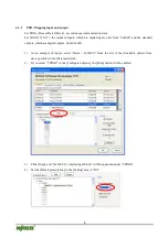
When you start up GP-Pro EX, the [Welcome to GP-Pro EX] window will appear. Select [New].
2)
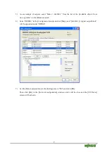
In the [Display Unit] setting screen, set the [Series] to GP-34**Series and the [Model] to
AGP-3400T-CA1M.
3)
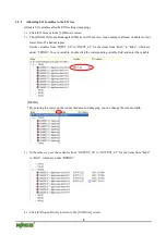
In the [Device/PLC] setting screen, click [New Logic] or [New Screen].
4)
Create screens and/or a logic program.

