29
10.3
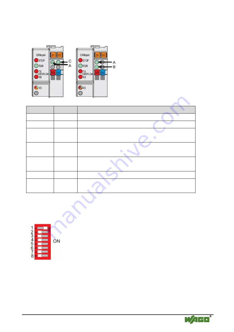
Display elements
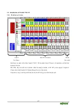
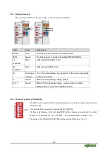
The operating condition of the bus coupler or node is signaled via LEDs.
LED
Color
Description
STOP
Red
The bus coupler / node is in the state STOP.
RUN
Green
The bus coupler / node is in the state OPERATIONAL.
Tx-
Overflow
Red
CAN transmitter buffer is full.
Rx-
Overflow
Red
CAN receiver buffer is full.
IO
Red/green
/orange
The “I/O” LED indicates the operation of the node and signals
faults encountered.
A
Green
Status of the operating voltage system
B or C
Green
Status of the operating voltage – power jumper contacts
(LED position is manufacturing dependent)
10.4
Hardware address (Module ID)
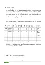
The DIP switch is used both for setting the baud rate of the bus coupler and for setting
the module ID.
This module ID is necessary for calculating the COB IDs.
The binary significance of the individual DIP switches increases according to the switch
number, i.e. the module ID 1 is set by DIP1 = ON, the module ID 8 by DIP4 = ON.
The nodes of the WAGO-I/O-SYSTEM can have module IDs from 1 to 127.

