2789-9080
Fieldbus Description
16
| Version: 1.1.0
Communication Module IO-Link
4
Fieldbus Description
4.1 Technology
4.1.1 IO-Link Technology
IO-Link defines a communication standard (acc. IEC 61131-9) for connecting both current
digital inputs/outputs and intelligent IO-Link devices to the controller level. IO-Link de-
vices describe sensors and actuators of the field level that have IO-Link functionality.
The IO-Link technology is predominantly used in the industrial sector of manufacturing
automation. With IO-Link, configuration, diagnostics and maintenance from the controller
are possible to the lowest field level in addition to process data communication. For ex-
ample, sensor failures can be diagnosed and localize in the controller directly.
With central parameter data storage in the IO-Link master and the possibility of project
development, connected devices can be simply replaced and configurations copied.
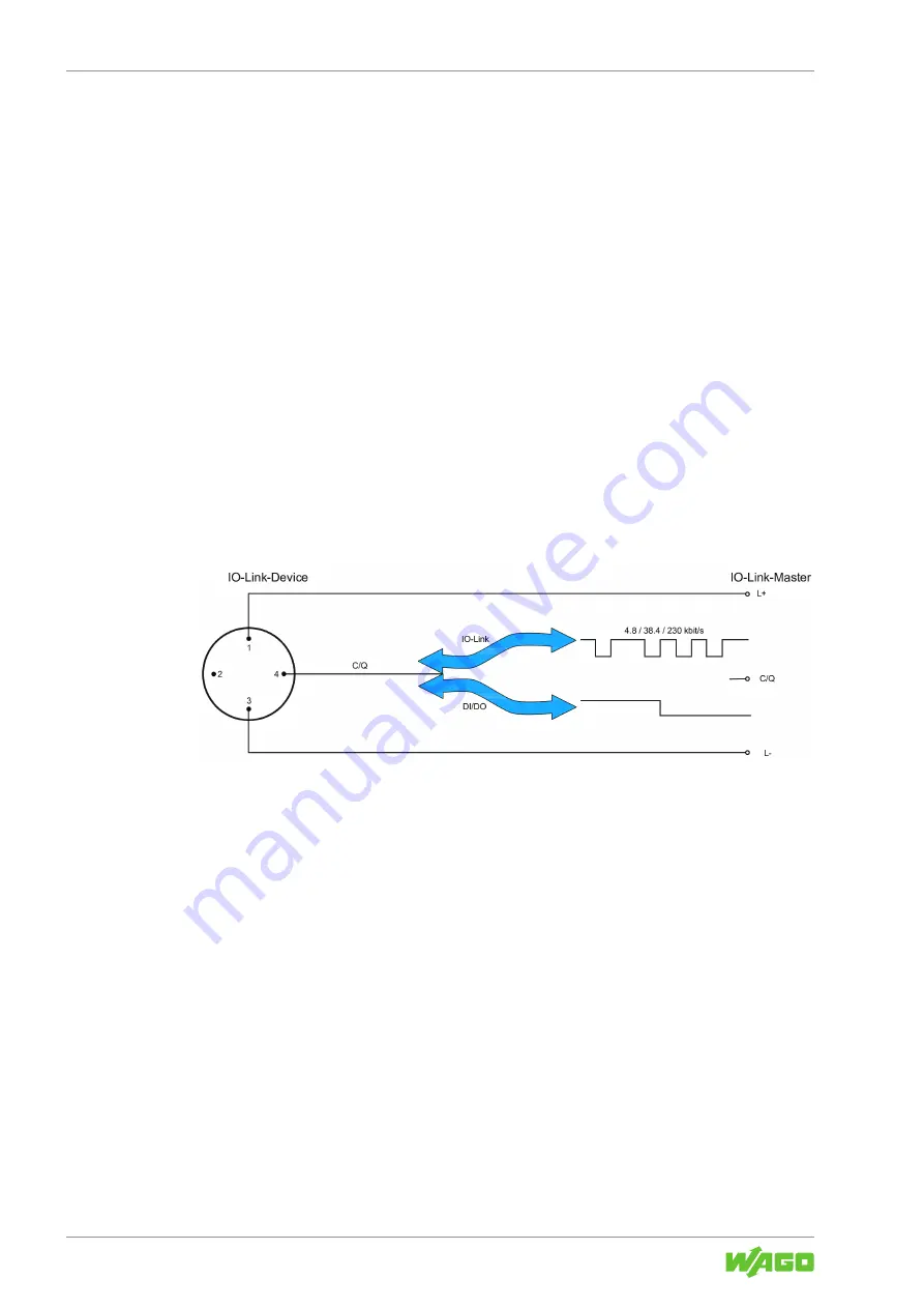
Communication occurs via serial point-to-point links in standard -3-wire technology. Both
data and diagnostic information as well as power supply are carried over the serial IO-
Link interface simultaneously.
Figure 6: 3-Wire Connection Technology (Based on Physics 2 of the IO-Link Specification 1.0.0)
Configuration of IO-Link devices is based on standardized description files “IO Device
Description” (IODD), which are provided by the device manufacturers and imported into
the respective configuration software. Thus, IO-Link devices can be integrated in current
automation systems and network structures independent of the bus systems used.
4.1.2 IO-Link – Functions
The production has the following functions:
• Reading the current settings from the lower-level device.
• Cyclic reading of the status from the lower-level device.
• Writing settings on the lower-level device.
• Controlling the lower-level device.
• Implementing the “Common Profiles” from IO-Link into the product.


