6
PC 1030
GB
2
IMPORTANT INFORMATION ON
PRODUCT LIABILITY
An EU directive valid since 01.01.1990 specifies that the manu-
facturer is only liable for his products if all the parts originate
from the manufactured or are approved by him, and if the
units are mounted and operated properly. If accessories or
spare parts from third parties are used, liability can be partially
or completely inapplicable. In extreme cases the responsible
authorities can prohibit the use of the entire unit (German in-
dustrial employer’s liability insurance association and factory
inspectorate).
With original WAGNER accessories and spare parts, compli-
ance with all safety regulations is guaranteed.
POWER
ERROR
SPEED
R
A
F
2
1
4
3
5
TECHNICAL DATA/ REQUIRED TOOLS/ OPERATING ELEMENTS
3
TECHNICAL DATA
PlastCoat 1030
Voltage:
230 V~, 50/60 Hz
Fusing:
16 A time-lag
Device supply cable:
5 m long, 3 x 2.5 mm
2
Motor output P
1
:
2.3 kW
Max. convey capacity (water):
10, 15, 20 l/min
(depending on the rotor/
stator)
Max. operating pressure:
40 bar
Max. granular size:
K6 mm
Dimensions L x W x H:
1150 x 550 x 620 mm
Container capacity:
50 l
Weight (PlastCoat 1030):
60 kg
Weight (Spray lance):
2.1 kg
Max. tyre pressure:
2.5 bar
Degree of protection:
IP 54
Max. sound pressure level:
70 dB (A)*
Atomizing air connection:
Rapid action coupling
DN 7.2 mm
Max. atomizing air pressure:
10 bar
Minimum required compressed
air volume:
320 l/min
Max. mortar hose length:
40 m (and 2.5 m hose
whip)
Max. delivery height:
20 m
* Place of measurement: 1 m distance from unit and 1.60 m
above reverberant floor.
4
REQUIRED TOOLS AND AUXILIARY
MATERIAL
Designation
Order no.
Pump sliding means
9992824
Loctite 243
9992511
5
OPERATING ELEMENTS AND
DISPLAYS ON DEVICE
1 Delivery volume controller 0-10
2 Selector switch for operating mode
3 Indicator light (Error)
4 Operating light (Power)
5 EMERGENCY STOP switch
A
R
F
“A” position = automatic
Basic setting for control with an automatic
spray lance
A
R
F
“F” position = manual activation
Switches on the mortar spraying machine.
This setting is required for:
• disassembling the pump unit
A
R
F
“R” position = reverse gear
This setting is required for:
• relieving pressure on the mortar hose
• assembling the pump unit
Содержание PLASTCOAT 1030
Страница 9: ...9 PC 1030 GB...
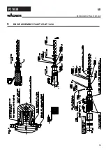
Страница 13: ...13 PC 1030 9 DRIVE ASSEMBLY PLAST COAT 1030 GB DRIVE ASSEMBLY PLAST COAT 1030...
Страница 15: ...15 PC 1030 GB...


