46
11. Adjustment of the spindle nuts with trapezoidal thread spindle
The spindle nuts of the milling machines are designed to be adjusted.
If a spindle nut of one of the three axis shows play, proceed as follows.
With spindle nuts with a ball screws, adjustment is neither required nor possible
11.1 X-axis
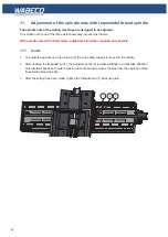
1. To adjust the spindle nut in the X-axis (2) the cross slide support is moved to the middle.
2. After undoing the threaded pin (1), the adjustment nut (3) is rotated slightly in a clockwise direction.
This rotation causes both nuts to tension each other and removes the play from the operation of the
trapezoidal thread spindle. .
3. After the setting has been made, tighten the threaded pin (1) back up again.
1
2
3
Содержание F1410 LF
Страница 41: ...41 7 Fitting and removing the tools 42 6 Spannen und Ausdrücken der Werkzeuge 1 2 3 4 5 ...
Страница 64: ...64 16 Drawings and legends 16 2 Electronic hood with 1 4 kW motor 16 2 2 CC F1410 LF 1 5 7 6 4 3 2 ...
Страница 98: ...98 16 Drawings and legends 16 12 Spindle Z axis with ball screws 16 12 1 F1410 LF F1410 LF hs ...
Страница 102: ...102 16 Drawings and legends 16 13 Lateral drive for Z axis with ball screws 6 4 5 4 3 2 1 7 12 8 9 10 11 14 13 ...
Страница 118: ...118 16 Drawings and legends 16 20 Control panel for 1 4 kW motor 12 1 11 18 2 4 10 8 7 9 6 3 5 5 5 13 14 15 16 17 ...
Страница 120: ...120 16 Drawings and legends 16 20 Control panel for 1 4 kW motor 7 2 3 8 1 6 10 9 9 10 5 4 11 12 13 14 15 16 17 ...
Страница 122: ...122 16 Drawings and legends 16 21 Control panel for 2 0 kW motor 5 12 1 11 5 10 9 8 7 6 18 2 3 4 5 13 14 15 16 17 ...
Страница 124: ...124 16 Drawings and legends 16 21 Control panel for 2 0 kW motor 7 2 3 8 1 11 12 13 14 15 16 17 ...
Страница 126: ...126 16 Drawings and legends 16 22 Support arm for control panel 1 2 3 4 5 6 8 9 5 4 7 9 8 ...

