40
7.
Fitting and removing the tools
The tool tightening and removing screw
has a fine
thread at the head, and a coarse thread on the shaft.
Due to this construction, a special procedure must be
followed when fitting and removing tools.
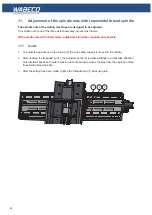
To make this easier to understand, the image shows a cut-away of the protective hood and the spindle
housing. The cross-section shows the tool screw (2) and the Allen key (1).
To change the tool, proceed as follows:
Tensioning tools with inner thread
1. Screw the tool tightening screw (2) clockwise using the Allen key (1) into the main spindle up to the
end of the thread
2. When the tool tightening screw (2) is at the end of the thread, undo by 2 - 3 turns
3. Now the tool (e.g. the collet chuck (5)) is inserted by hand from below into the ball of the tool spindle
(3) and screwed anti-clockwise onto the tool tightening screw (2). The Allen key (1) is used to hold
the tool tightening screw (2) in place.
4. When the tool has been hand-tightened, the holding bolt (4) is used to hold the tool spindle (3) and
tighten the tool tightening screw (2) clockwise without great strength using the Allen key (1
).
Removing tools with an inner thread
1. Hold the tool spindle (3) with the holding bolt (4)
2. Undo the tool tightening screw (2) using the Allen key (1) by turning anti-clockwise. To undo the tool
tightening screw (2) turn the Allen key (1) forcefully until the cone comes undone.
3. Now unscrew the tool clockwise by hand from the tool tightening screw (2) and remove from below
from the ball of the tool spindle (3)
Tensioning tools with take-up(without inner thread)
4. Undo the tool tightening screw (2) using the Allen key (1) far enough that the take-up is no longer up
against that tool tightening screw (2).
5. Press the tool with a forceful push into the tool spindle (3).
Removing tools with take-up(without inner thread
1. Insert the holding bolt (4) in the tool spindle (3) and hold with one hand.
2. Rotate the Allen key (1) clockwise, this releases the tool which will fall out of the tool spindle (3). In
order to prevent damages, place something under the tool to catch it gently
Содержание F1410 LF
Страница 41: ...41 7 Fitting and removing the tools 42 6 Spannen und Ausdrücken der Werkzeuge 1 2 3 4 5 ...
Страница 64: ...64 16 Drawings and legends 16 2 Electronic hood with 1 4 kW motor 16 2 2 CC F1410 LF 1 5 7 6 4 3 2 ...
Страница 98: ...98 16 Drawings and legends 16 12 Spindle Z axis with ball screws 16 12 1 F1410 LF F1410 LF hs ...
Страница 102: ...102 16 Drawings and legends 16 13 Lateral drive for Z axis with ball screws 6 4 5 4 3 2 1 7 12 8 9 10 11 14 13 ...
Страница 118: ...118 16 Drawings and legends 16 20 Control panel for 1 4 kW motor 12 1 11 18 2 4 10 8 7 9 6 3 5 5 5 13 14 15 16 17 ...
Страница 120: ...120 16 Drawings and legends 16 20 Control panel for 1 4 kW motor 7 2 3 8 1 6 10 9 9 10 5 4 11 12 13 14 15 16 17 ...
Страница 122: ...122 16 Drawings and legends 16 21 Control panel for 2 0 kW motor 5 12 1 11 5 10 9 8 7 6 18 2 3 4 5 13 14 15 16 17 ...
Страница 124: ...124 16 Drawings and legends 16 21 Control panel for 2 0 kW motor 7 2 3 8 1 11 12 13 14 15 16 17 ...
Страница 126: ...126 16 Drawings and legends 16 22 Support arm for control panel 1 2 3 4 5 6 8 9 5 4 7 9 8 ...


