123
16. Drawings and legends
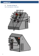
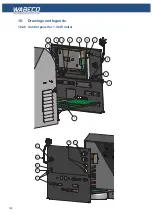
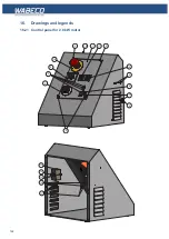
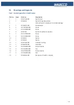
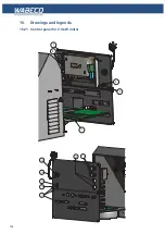
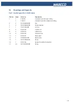
16.21 Control panel for 2.0 kW motor
Part no. Items
Order no.
Description
1
1
51401539-0001
Switch cover
2
1
51500600
Switch for operating modes
3
LEDs with switch (contained in controller package)
4
1
51500801-0001
Potentiometer
5
4
16179810003095
Screw
6
1
16191200004025
Screw
7
2
51501304
Symbol for earthed connection
8
1
16191200004012
Screw
9
2
16191200003010
Screw
10
1
51500601
Switch
11
1
51500602
Switch
12
1
51401509-0001
Controller housing
13
1
51500800-0001
Noise filter
14
2
16167980003000
Fanned washer
15
2
16193400003000
Nut
16
4
16167980004000
Fanned washer
17
4
16193400004000
Nut
18
1
51500624-0001
Emergency off switch, complete
Содержание F1410 LF
Страница 41: ...41 7 Fitting and removing the tools 42 6 Spannen und Ausdrücken der Werkzeuge 1 2 3 4 5 ...
Страница 64: ...64 16 Drawings and legends 16 2 Electronic hood with 1 4 kW motor 16 2 2 CC F1410 LF 1 5 7 6 4 3 2 ...
Страница 98: ...98 16 Drawings and legends 16 12 Spindle Z axis with ball screws 16 12 1 F1410 LF F1410 LF hs ...
Страница 102: ...102 16 Drawings and legends 16 13 Lateral drive for Z axis with ball screws 6 4 5 4 3 2 1 7 12 8 9 10 11 14 13 ...
Страница 118: ...118 16 Drawings and legends 16 20 Control panel for 1 4 kW motor 12 1 11 18 2 4 10 8 7 9 6 3 5 5 5 13 14 15 16 17 ...
Страница 120: ...120 16 Drawings and legends 16 20 Control panel for 1 4 kW motor 7 2 3 8 1 6 10 9 9 10 5 4 11 12 13 14 15 16 17 ...
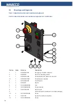
Страница 122: ...122 16 Drawings and legends 16 21 Control panel for 2 0 kW motor 5 12 1 11 5 10 9 8 7 6 18 2 3 4 5 13 14 15 16 17 ...
Страница 124: ...124 16 Drawings and legends 16 21 Control panel for 2 0 kW motor 7 2 3 8 1 11 12 13 14 15 16 17 ...
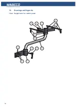
Страница 126: ...126 16 Drawings and legends 16 22 Support arm for control panel 1 2 3 4 5 6 8 9 5 4 7 9 8 ...


