14
1.
Important safety notes
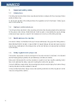
1.6
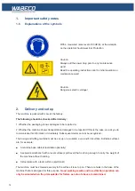
Explanations of the symbols
With a measured noise level of 80 dB (A) at the workpla-
ce the operator should wear Ear Protection.
Caution:
Always pull the power plug prior to any maintenance
work!
Read the operating instructions prior to initial operation or
maintenance work!
Caution:
Dangerous electric voltage!
2.
Delivery and set up
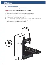
The machine is packed with care at the factory.
The following should be checked after delivery:
1. Whether the packaging shows damages to be reported or
2. Whether the machine shows transportation damages to be reported If this is the case, we ask you to
communicate this information immediately. Subsequent claims cannot be recognised.
The boring and milling machine must be set up on a suitable, even and firm surface. Suitable surfaces
are, for example:
■
A machine base cabinet (available optionally)
■
A separate workbench with a level surface (spirit level) that is strong enough to carry the weight of
the machine without bending.
■
A steel plate with a level surface (spirit level)
The machine must be screwed securely to the surface it is set up on. There are holes in the base of the
machine that are designed for this purpose.
Good working results and low-vibration operation can
only be ensured when the prerequisites for fixture as set out above are maintained.
Содержание F1410 LF
Страница 41: ...41 7 Fitting and removing the tools 42 6 Spannen und Ausdrücken der Werkzeuge 1 2 3 4 5 ...
Страница 64: ...64 16 Drawings and legends 16 2 Electronic hood with 1 4 kW motor 16 2 2 CC F1410 LF 1 5 7 6 4 3 2 ...
Страница 98: ...98 16 Drawings and legends 16 12 Spindle Z axis with ball screws 16 12 1 F1410 LF F1410 LF hs ...
Страница 102: ...102 16 Drawings and legends 16 13 Lateral drive for Z axis with ball screws 6 4 5 4 3 2 1 7 12 8 9 10 11 14 13 ...
Страница 118: ...118 16 Drawings and legends 16 20 Control panel for 1 4 kW motor 12 1 11 18 2 4 10 8 7 9 6 3 5 5 5 13 14 15 16 17 ...
Страница 120: ...120 16 Drawings and legends 16 20 Control panel for 1 4 kW motor 7 2 3 8 1 6 10 9 9 10 5 4 11 12 13 14 15 16 17 ...
Страница 122: ...122 16 Drawings and legends 16 21 Control panel for 2 0 kW motor 5 12 1 11 5 10 9 8 7 6 18 2 3 4 5 13 14 15 16 17 ...
Страница 124: ...124 16 Drawings and legends 16 21 Control panel for 2 0 kW motor 7 2 3 8 1 11 12 13 14 15 16 17 ...
Страница 126: ...126 16 Drawings and legends 16 22 Support arm for control panel 1 2 3 4 5 6 8 9 5 4 7 9 8 ...

