


16
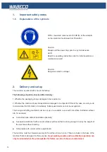
2.
Delivery and set up
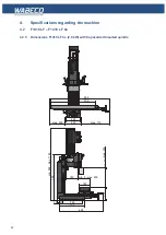
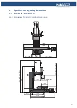
2.2
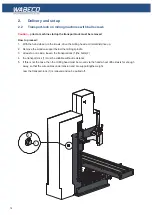
Transport-lock on milling machines with ball screws
Caution –
prior to machine startup the transport-lock must be removed
How to proceed:
1. With the hand wheel via the Z-axis, drive the milling head a minimal distance up.
2. Remove the wooden support below the milling spindle
3. at least on one side, loosen the transport-lock (1)the bolts (2)
4. the transport-lock (1) must be slidable without resistance
5. if this is not the case, then the milling head must be moved via the hand wheel ofthe Z-axis far enough
away, so that the wire cables under tension and are supportingthe weight.
now the transport-lock (1) is relieved and ca be pulled off.
A ( 1 : 1 )
1
2
Содержание F1410 LF
Страница 41: ...41 7 Fitting and removing the tools 42 6 Spannen und Ausdrücken der Werkzeuge 1 2 3 4 5 ...
Страница 64: ...64 16 Drawings and legends 16 2 Electronic hood with 1 4 kW motor 16 2 2 CC F1410 LF 1 5 7 6 4 3 2 ...
Страница 98: ...98 16 Drawings and legends 16 12 Spindle Z axis with ball screws 16 12 1 F1410 LF F1410 LF hs ...
Страница 102: ...102 16 Drawings and legends 16 13 Lateral drive for Z axis with ball screws 6 4 5 4 3 2 1 7 12 8 9 10 11 14 13 ...
Страница 118: ...118 16 Drawings and legends 16 20 Control panel for 1 4 kW motor 12 1 11 18 2 4 10 8 7 9 6 3 5 5 5 13 14 15 16 17 ...
Страница 120: ...120 16 Drawings and legends 16 20 Control panel for 1 4 kW motor 7 2 3 8 1 6 10 9 9 10 5 4 11 12 13 14 15 16 17 ...
Страница 122: ...122 16 Drawings and legends 16 21 Control panel for 2 0 kW motor 5 12 1 11 5 10 9 8 7 6 18 2 3 4 5 13 14 15 16 17 ...
Страница 124: ...124 16 Drawings and legends 16 21 Control panel for 2 0 kW motor 7 2 3 8 1 11 12 13 14 15 16 17 ...
Страница 126: ...126 16 Drawings and legends 16 22 Support arm for control panel 1 2 3 4 5 6 8 9 5 4 7 9 8 ...


