background image


C H A P T E R   6  

Warranty 

Your VTL amplifier/amplifier is covered by a limited warranty against defects in materials and workmanship for a 
period of 90 days from date of purchase by the original purchaser only when purchased from an authorized VTL dealer 
only. A further optional limited non-transferable five-year warranty is available to the original purchaser only upon 
proper registration of ownership within 30 days of date of first purchase. The warranty period begins on date of first 
sale to the end user, or one year after shipment from the VTL factory, whichever is the earlier. 

Proper registration is made by filling out and returning to the factory the warranty card attached to this general warranty 
statement, along with a copy of the original sales receipt as proof of the original date of purchase, within 30 days of 
purchase. Only one registration card is issued with each unit. If the warranty registration card has already been removed 
then this is not a new unit, and is therefore not warranted by the factory. If you believe this to be a new unit then please 
contact the factory with the details of purchase. 

This warranty is provided by the dealer where the unit was purchased, and by VTL Amplifiers Inc. Under the terms of 
the warranty defective parts will be repaired or replaced without charge, excepting the cost of tubes.  A six-month 
warranty on tubes is available with the correct recording of the serial number of the amplifier on your warranty 
registration card and mailing it with your purchase receipt to VTL. 

If a VTL product fails to perform properly under the above warranty then the purchaser's sole remedy shall be to 
return the product to the authorized VTL dealer or to VTL Amplifiers Inc, where the defect will be repaired without 
charge for parts and labor. The product will then be returned via prepaid, insured freight, method and carrier to be 
determined solely by VTL Amplifiers Inc. All returns to the factory must be in the original packing and accompanied 
by a Return Authorization, (new packing will be supplied for a nominal charge if needed), accompanied by a written 
description of the defect. This must be shipped to VTL Amplifiers Inc via insured freight at the customer's own 
expense. Charges for unauthorized service and transportation costs are not reimbursable under this warranty, and all 
warrantees, express or implied, become null and void where the product has been damaged by misuse, accident, 
neglect, modification, tampering or unauthorized alteration by anyone other than VTL Amplifiers Inc., including the 
use of non-factory approved tubes. 

This warranty applies only to units used in residential non-commercial use. The warrantor assumes no liability for 
property damage or any other incidental or consequential damage, whatsoever which may result from failure of this 
product. Any and all warrantees of merchantability and fitness implied by law are limited to the duration of the 
expressed warranty. All warrantees apply only to VTL products purchased and used in the USA. 

Some states do not allow limitations on how long an implied warranty lasts, so the above limitations may not apply to 
you. Some states do not allow the exclusion or limitation of incidental or consequential damages, so the above 
exclusion may not apply to you. 

This warranty gives you specific legal rights and you may also have other rights that vary from state to state. 

S-400 Amplifier Owner’s Manual 
VTL 

57 


Содержание S-400 II series

Страница 1: ...VTL S 400 Series II Reference Stereo Amplifier Owner sManual ...

Страница 2: ...ent may be reproduced or transmitted in any form or by any means electronic or mechanical for any purpose without the express written permission by VTL Version History Version 1 0 August 26 2014 Part Number OM S 400 Copyright 2014 by VTL Amplifiers Inc All rights reserved 4774 Murrieta Street Suite 10 Chino CA 91710 USA Phone 909 627 5944 Fax 909 627 6988 Email mail vtl com http www vtl com ...

Страница 3: ...8 Front Panel Indicators 18 AC Voltage Setting 19 AC Power Source 20 Connection to the AC 20 Powering On the Amplifier 20 Ground Loop Hum 23 Setting the Operating Mode 23 Muting the Amplifier 24 Tube Bias and Top deck Indications 24 Using the DF switches 27 DF Switch Settings 27 Remote Control and Communications 29 Using a 12V trigger to power the amplifier on or off 29 Using the Amplifier with an...

Страница 4: ...e 47 Changing Tubes 48 Changing the Screen Plate Logic B Input Filament Fuses 51 Cleaning 52 Troubleshooting 52 CHAPTER 5 55 SPECIFICATIONS 55 CHAPTER 6 57 WARRANTY 57 APPENDIX 58 Appendix I Quick Reference Summary of indicators 58 Appendix II Individual tube hour log 60 Warranty Registration 61 Service Notes 61 ...

Страница 5: ...esence are appreciated by the most serious and discerning music and film lovers We thank you for selecting this amplifier for your home audio theater system and we wish you many hours of enjoyment for years to come In order to get the most benefit from your purchase we recommend that you take sufficient time to familiarize yourself with the features of this product Please take a moment to read thr...

Страница 6: ...king of the entire signal path Upgrades include a fully balanced differential input stage driving a differential phase splitter and a lower impedance push pull output stage with a dramatically improved fully balanced and enhanced interleaved and coupled output transformer The S 400 Reference stereo amplifiers gain further sonic benefits with a shorter faster and fully balanced negative feedback lo...

Страница 7: ...the amplifier is shut down to protect the circuitry and faults are indicated on the front panel along with the blinking LED on the top deck next to the tube that caused the fault shutdown to make diagnosis and tube replacement easy The logic controlled automatic bias system is designed to keep the tubes at peak performance and operates completely outside of the signal path The tube biasing circuit...

Страница 8: ...s that might come in contact with the unit and to the unit itself and proper RF shielding cannot be attained without a secure ground connection Damage to the unit that is the result of improper AC connection and grounding will not be covered under the warranty Prior to connecting this amplifier to any audio or video equipment in your system make sure this unit s power and the rest of the equipment...

Страница 9: ...ldren it is recommended that you remove power cables when the equipment is not in use Servicing Do not attempt to service the amplifier beyond the procedures described in this manual For all other service and questions please contact your authorized VTL dealer or the factory Operational Warnings It is critical for proper sonic performance of this component that it be properly configured for the mo...

Страница 10: ...e amplifier and allow the tubes to cool down before attempting to work with the tubes Tube components can be heavy and awkward to lift with the weight unevenly distributed and you should not attempt to move the unit without help The amplifier weighs approximately 250 lbs 113 Kg Do not exceed fuse ratings or attempt to bypass any fuses as this can cause an extremely hazardous condition and will voi...

Страница 11: ... other than the bottom side and on a stable surface Setting it on any other side may damage protruding components SAVE THE CRATES AND ALL PACKAGING FOR FUTURE SHIPMENT Warning This unit is extremely heavy and weighs about 200 lbs Unpacking should be done by two or more people who are capable of lifting a heavy load Ensure that the amplifier would not fall and injure someone Do not attempt to lift ...

Страница 12: ... Spare Fuses and spare output tubes 1 set of four spiked feet for each amp This Owner s Manual Quick Reference Sheet VTL Quality Assurance and test printout and a VTL product warranty registration card The following sets of instructions apply to both crates from this point on After removing the top accessory cover then you may proceed with removing the screws from around the bottom of the crate al...

Страница 13: ...ifier remove the 4 spiked feet from the Spare Parts kit that was included with this unit Tilting the unit to one side at a time install the feet into the threaded holes in the aluminum base of the amplifier in the approximate locations pictured 5 Return the plastic bag and the tie straps to the base of the crate place the crate box onto the base and screw it together with the same screws that were...

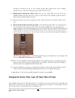
Страница 14: ...g screws socket heads are located on the right side panel screw 2 and 7 counting from the side closest to the front panel The third screw Phillips head is located on the top right hand corner of the back panel After the three long screws are removed gently lift up the top cover Enclosed in the spare package are the shorter replacements screws Replace the right side panel 2 and 7 screws with two 6 ...

Страница 15: ... the amplifier is in your system and operational please take the time to read the rest of the information in this manual It will give you the in depth perspective into all the functions your amplifier is capable of delivering and how to take advantage of the many sophisticated functions built into your amplifier to inform you of its internal status Step 1 Find a location for the unit We recommend ...

Страница 16: ... sure that the subwoofer input is fully balanced and that neither phase can become grounded Please consult your authorized VTL dealer or the VTL factory customer support department if you have any questions on the fully balanced connection of the amplifier Step 3 Connect the Preamplifier to the Amplifier Make sure all units are turned OFF connect the preamplifier s output to the amplifier s input ...

Страница 17: ...urn on the Amplifier Locate the Power rocker switch at the back of the Amplifier on the bottom right hand corner next to the AC power inlet Turn the switch up to the ON position For the first 10 seconds you should see four dots scrolling on the display window indicating that the amplifier is checking its internal status and when it is ready to go into the standby mode four blue bars will be displa...

Страница 18: ...t panel or both not showing the INVERT indication depending upon the preamplifier used Congratulations You have just completed the Quick Start section for your new amplifier s operation You may now wish to read the rest of this manual while relaxing and listening to some of your favorite music S 400 Amplifier Owner s Manual VTL 14 ...

Страница 19: ...C Power inlet input fuses and the fuse tester Input Output Interface Panel The Input Output Interface Panel contains the following The Screen Fuse is the output tube s screen fuse The Plate Fuse is the output tube s plate fuse CAUTION High voltages present For continued protection against risk of fire replace only with fuses of same type and rating The IR Receiver is used for receiving infrared si...

Страница 20: ...ote the correct phase when connecting to the loudspeaker Red or to and Black or to Warning The S 400 Series II amplifier is a fully balanced design with a balanced output Care should be taken so that neither output is ever grounded Warning Do not connect a sub woofer to the output of the amplifier unless you are sure that the subwoofer input is fully balanced and that neither phase can become grou...

Страница 21: ...properly configured for the correct mode of operation If a balanced signal is applied to the inputs the unit should be configured for balanced operation and vice versa Since the two inputs differ in gain for proper channel balance it is recommended that all amplifiers in the system be set to the same input WARNING This is a very high powered amplifier capable of extremely high levels Do not change...

Страница 22: ...he row is used to select the operating mode of the amplifier either Tetrode mode green light or Triode mode red light The MODE can be selected while the amplifier is in operating mode only MUTE When the amplifier is powered up pressing the MUTE button on the right of the row toggles the amplifier between MUTEd low current state no output indicated by a steady red MUTE light and operating state whe...

Страница 23: ...t to the correct AC voltage for the country where purchased and is not user or field re settable The voltage setting is marked on the serial number badge located on the rear panel of the amplifier If the marking has been defaced or removed then contact the factory before connecting this component to any AC voltage source WARNING Check to make sure that the voltage setting is correct for your local...

Страница 24: ...c shielding cannot be attained without a secure ground connection This amplifier contains static sensitive components and damage to the unit as a result of either improper AC connection or improper grounding will not be covered under the warranty The sensitive microprocessors in this component can be affected by external noise and proper operation cannot be guaranteed without a noise free AC groun...

Страница 25: ... on indicating some type of fault in the system the amplifier cannot be powered on In this case please refer to the Fault Indications section in this chapter and contact your authorized VTL dealer or the factory for assistance Front Panel indication Standby mode 5 If the display shows the steady the amplifier can be powered on via one of the following methods The red POWER button on the front pane...

Страница 26: ...ssor controlled timing technique to enhance tube life by warming the tubes up slowly and applying the high tension with a gentle ramp up only after the tubes are properly warm and ready to conduct The autobias system biases the tubes into cutoff and the fault sensing system monitors continuously for faults During this warm up period the amplifier is in the muted mode and will stay in the muted sta...

Страница 27: ... automatically after the user initiates the command The MODE light changes to red when the amplifier is in Triode mode The two modes are different in output power and voltage gain with tetrode mode being the higher of the two Tetrode mode is typically used for large scale symphonic rock or big band music to provide the proper resolution and power required and triode mode is typically used for smal...

Страница 28: ...tages are at their prescribed levels with the output stage biased into a low current draw level In the MUTEd mode the heat output is therefore substantially lowered to a point that saves power and uses very little tube life and is still sufficient to keep the amplifier warm and ready to come up to full power within 30 seconds Leaving the amplifier in the MUTEd state for short periods between liste...

Страница 29: ...the output tubes and if not suppressed are normally lit when the amplifier is powered on and in the operating mode and sometimes blink on and off to indicate bias status In the case of a tube fault whether normal bias LED activity is suppressed or not the relevant tube s LED flashes quickly to identify the tube that needs replacement and during diagnostic functions these LEDs are also used to iden...

Страница 30: ...iased User should replace the tube as soon as possible at the end of the listening session One tube LED is blinking rapidly and the red front panel TUBE light is flashing Display Window shows tube number The Auto bias has detected that this tube has a critical fault and the amplifier has been shut down Replace faulty tube and reset the Tube fault See Chapter 4 The amplifier is in idle mode and tub...

Страница 31: ...itches There are three possible settings of the DF switches Low Medium and High Please check to make sure that the switches in both channels are in the same position There is no right or wrong position and the switches are provided to allow adjustment to better suit the listener s taste and to offer better control to loudspeakers that may need it DF Switch Settings 1 LOW Both switches are position...

Страница 32: ...ting allows for better loudspeaker control and may be the most suitable for wide range of speaker types MED DF Setting 3 HI Both switches are towards the back of the amplifier Best loudspeaker control but may have some impact on sound quality S 400 Amplifier Owner s Manual VTL 28 ...

Страница 33: ...p if the rear rocker switch is in the ON position and when the hold is released the amplifier automatically powers down In all cases the front panel power button takes precedence to power down If the amplifier is powered on via the front panel button then applying the trigger voltage will not cause a change If either the trigger voltage is released or the front panel power button is pressed the am...

Страница 34: ... and standard ASCII text strings using pre defined commands as listed below in the summary of all the control functions that can be performed on the front panel and the expected results on the display window and the RS 232 port The RS232 communication port is designed to interface with central command systems to enable the amplifiers to be located and operated remotely and allows the user to inter...

Страница 35: ...the amplifier READTEMP F C For displaying the unit temperature in degrees Fahrenheit or Celsius PHASE For querying the phase setting of the amplifier PHASE ZERO PHASE 180 BIASLEDS ON OFF For unsuppressing and suppressing the normal bias LED activity COUNTDN ON OFF For muting the power up countdown TUBEFLT CLEAR For querying tube fault status and to clear a tube fault VTL Returns factory contact in...

Страница 36: ...d as well as the master processor The master processor is socketed and can be updated with any new software versions or specially requested features The diagnostic buttons are used for accessing all of the diagnostics that this amplifier is equipped with allowing the user access to the most important operating features and controls WARNING Be careful not to touch the master processor pins or any o...

Страница 37: ...perate mode Press the MUTE button while holding down the TUBE BIAS button to turn the LEDs off RS 232 BIASLEDS OFF Press the MUTE button while holding down the TUBE BIAS button to turn the LEDs back on RS 232 BIASLEDS ON Top deck LEDs toggle between on and off Note Only normal bias activity is suppressed fault and tube identification is not suppressible S 400 Amplifier Owner s Manual VTL 33 ...

Страница 38: ...al time becomes five digits For instance at 10 000 hours the display indicates 1 000 A decimal in the second digit indicates 6 digits ie 100 000 hours and so on RS 232 command TOTLTIME Display Tube Time A resettable time log that the user can use to tell the amount of time that a set of tubes has been in the amplifier This function is accessible either in Standby mode or operate mode When user pre...

Страница 39: ...ions later in this chapter Temp Displays the temperature of the rear heatsink either in degrees Celsius or Fahrenheit This button has a dual function When used alone this button is a temperature button When used simultaneously with some of the other buttons it acts as a reset button See Fault section in this chapter This function is accessible either in Standby mode or operating mode RS 232 comman...

Страница 40: ...operation the heat sink should not reach 50 degrees C unless there is inadequate ventilation or very high power requirements for extended time periods See Fault Indications later in this chapter S 400 Amplifier Owner s Manual VTL 36 ...

Страница 41: ...e amplifier has been in operate mode continuously for at least 1 hour This function is accessible in operate mode only Mute the preamp to prevent music signal from coming through to the amplifier Muting the amplifier invalidates the tube bias test Pressing the BIAS button displays the tube number while the button is held down That tube s bias setting is displayed for 2 seconds when the button is r...

Страница 42: ...afely Remove any fuses that may be inside either of the two fuse holders in the test area The Fuse holders are connected in parallel and so the test will be invalid if the user has fuses in both fuse holders Note that there are two sizes of fuses in the amplifier Remove the fuse to be tested from its original fuse holder and install it in the appropriate sized fuse holder To test either type of fu...

Страница 43: ... RS 232 commands Then enter the VIEWERR command into the Hyperterminal window The error messages stored in the buffer will be displayed Copy and paste the entire contents of the VIEWERR commands to a WORD document and email this information to your dealer or to the VTL factory Fault Indications This amplifier uses a comprehensive fault sensing system to self diagnose all critical operating areas p...

Страница 44: ...either open or out of the socket and the autobias system has been unable to bring it up to full power The tube number is displayed on the front panel display and the top deck LED next to the indicated tube is blinking steadily to show the exact location of the tube The steady blinking on the open tube will continue to blink while the amplifier is in the standby condition or while music signal is p...

Страница 45: ...rcuits In this condition the amplifier is in the standby mode with the LED indicators showing what to do to re start the amplifier The tube number is displayed on the front panel display and the top deck LED next to the indicated tube is blinking quickly to show the exact location of the tube The steady blinking on the failed tube will continue to blink while the amplifier is in the standby condit...

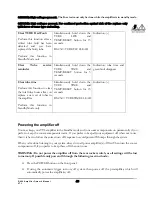
Страница 46: ...using the POWER button on the front panel WARNING Do not attempt to clear the fault and re power without first replacing the faulty output tube as doing so could potentially damage the circuitry If power to the amplifier is lost after a red tube fault shutdown and before the fault is cleared the fault is retained in memory until the next power up where the fault will have to be cleared before powe...

Страница 47: ... whether power to the amplifier is lost or not as the AC voltage sensing re activates whenever AC power is applied to the amplifier When the amplifier s AC fault condition is removed the front panel POWER light turns off and the display indicates a steady indicating that the amplifier can be re powered If the amplifier was on and shuts down the steady red power light to indicate what happened If a...

Страница 48: ... depending upon power levels that the amplifier is operated at The service reminder is used to remind the user to check the condition of the output tubes with a quantitative test and then replace any faulty gassy or weak tubes We recommend that the tubes be replaced when the reminder is displayed and then the service indicator can be re set and it will reappear after the next 3000 hours to remind ...

Страница 49: ...dby Mode only Simultaneously hold down the TUBE TIME and TEMP RESET button for 15 seconds RS 232 TUBETIME CLEAR Indication Powering the amplifier off You may keep your VTL amplifier in the Standby mode and your source components on permanently if you prefer to keep the source components warm If you prefer to keep all your equipment off when not in use then it is best to follow the correct turn off...

Страница 50: ...s power down and displays and discharges high voltage power supplies Last used modes are saved for next power up RS 232 command POWER OFF To avoid unplanned power ups turn the rear panel power rocker switch to OFF position if you don t plan to use the amplifier for an extended period of time S 400 Amplifier Owner s Manual VTL 46 ...

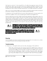
Страница 51: ...fier to a like new sound quality The TUBE TIME diagnostic function is designed to inform you of the cumulative hours your tubes have been in use since the last replacement When the total Tube Time reaches 3000 the TUBE GREEN LED bar will light up and the Display Window will show the number 3000 This serves as a reminder that you should change your entire set of tubes and after the change reset you...

Страница 52: ...of your body or hanging jewelry to come into contact with any part of the circuit inside the unit Removing the top cover to gain access to the tubes When the amplifier was first shipped from the factory the top cover was installed with locking screws The screw should be removed by the customer for easy access to the tubes inside the amplifiers User input The top cover of the amplifier is fitted wi...

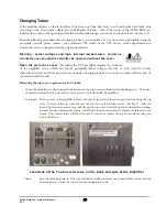
Страница 53: ...his amplifier you should first power the unit down turn off the Power rocker switch from the rear panel amd unplug the unit from the wall outlet Let the amplifier stay powered off for at least 15 minutes before working with it Make sure the tubes are cool before you touch them Carefully remove the top cover and store it in a safe place See the procedure in the previous page on how to remove the to...

Страница 54: ... completely inserted into the socket it should be firmly seated and does not give in to any movement at all when you try to rock it gently If the socket appears loose and not making contact with any or all of the tube pins contact VTL for help 6 For the larger Power tubes there is a locating pin in the middle of the tube 8 pin octal tubes Make sure that these locators go into the side of the socke...

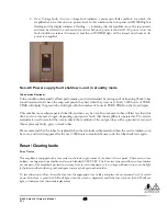
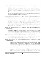
Страница 55: ...ons at the same time for 15 seconds until the front panel fault indicators turn off and the display shows indicating that the amp is in Standby mode See Chapter 3 the section on Reset Red Tube Fault for more details 10 Power on the amplifier from the Standby Mode to the Operating mode by touching the Power button on the front panel The amplifier starts its countdown sequence and resets and rebiase...

Страница 56: ...se direction to lock it in place Use the same procedure to replace the output stage protection fuses WARNING For continued protections against fire hazard only replace the fuse with the same type and rating as was specified for the amplifier by the VTL factory If you have problems locating the correct fuse contact your VTL dealer or the VTL factory service department WARNING Before powering on the...

Страница 57: ...either contact your dealer or the VTL factory to try to resolve this problem 4 I am getting a noise and hum coming from my system when I plug in a video source What can I do to eliminate the noise The noise may be coming in from your video cable system First disconnect the VCR from the system to see if this will solve the problem If it does then you will need to try to lift the ground from the cab...

Страница 58: ...e rectified internally and requires repair by a service technician After repair the technician will also reset the processor so that the unit can be powered up again S 400 Amplifier Owner s Manual VTL 54 ...

Страница 59: ...ing Input impedance 48K Ohms Balanced Input Common Mode Rejection Ratio 60 dB S N Ratio 300 W Tetrode S N Ratio 150 W Triode 90dB 120 Hz Power consumption Idle 560 W Full Power 1600 W Secondary DC Volt Fuse Ratings Plate 2 5A Fast acting 600V Screen 3 4A Fast acting 600V AC Fuse ratings Logic 1 0 Amp Slo Blo 120V 220V 240V B 120V 20 Amp Slo Blo 240V 10 Amp Slo Blo Input 120V 2 Amp Slo Blo 240V 1 A...

Страница 60: ...Crate Dimensions 33 x 28 x 42 inches S 400 Amplifier Owner s Manual VTL 56 ...

Страница 61: ...purchaser s sole remedy shall be to return the product to the authorized VTL dealer or to VTL Amplifiers Inc where the defect will be repaired without charge for parts and labor The product will then be returned via prepaid insured freight method and carrier to be determined solely by VTL Amplifiers Inc All returns to the factory must be in the original packing and accompanied by a Return Authoriz...

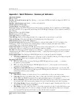
Страница 62: ...safe level to indicate re power allowed Power supply faults Slow flashing red POWER lighted text on front panel and relevant display AC power supply fault Incorrect AC voltage low or high Alternately flashing AC voltage setting and to indicate power up not available until correct voltage sensed Regulator fault modes OC over current Plate or Screen Flashing red POWER lighted text and steady to indi...

Страница 63: ...uttons for 15 seconds until clear response from display Service reminder Operate mode only Reset by holding down TUBE TIME and RESET for 5 seconds until TUBE green led bar and TUBE TIME on 7 seg display turns off TUBE LIFE Standby mode only Clear tube fault stored value by holding down the TUBE LIFE button and the RESET button for 15 seconds until clear signal received from 7 seg display Stored Bi...

Страница 64: ...er and total time on first installation of the tube To find the amount of time that tube has been in the amplifier for then subtract that number from the current total time Tube Number Total Time when tube was Installed Total Time Tube has been in use Current Total Time Install Time 1 2 3 4 5 6 7 8 9 10 11 12 S 400 Amplifier Owner s Manual VTL 60 ...

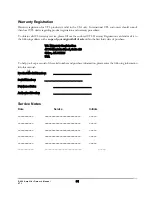
Страница 65: ...te 10 Chino CA 91710 USA To help you keep a record of the serial number and purchase information please enter the following information into this manual Product Model Number ___________________________ Serial Number ___________________________ Purchase Date ___________________________ Authorized Dealer ___________________________ Service Notes Date Service Initials ___________ ____________________...

Отзывы: