46
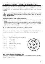
Proceed as follows for connection:
Connect the connecting cables of the remote sockets as illustrated:
V
Voltage setting “V”
• Connection 2 to the plus pole (+) of the
external control voltage.
• Connection 4 to the minus pole (-) of the
external control voltage.
Current setting “I“:
• Connection 3 to the plus pole (+) of the
external control volltage.
• Connection 4 to the minus pole (-) of
the external control volltage
The voltage on the remote control connection must not exceed 5 V.
The connections must not be shorted.
1. Switch off the power unit and then connect the remote socket to the rear
remote connection. Screw on the external fastening ring.
2. Turn the voltage of the external voltage source to 0 V.
3. Switch on the power unit.
4. Put the MODE switch (8) on the rear into the “Remote Ctrl” position. The
“REAR CONTROL” (2) display is lit.
5. The desired output value can now be set through the external voltage
source. Control the complete adjustment area for correct function. The
output voltage can be monitored in the display.
Short-circuit the rear main output (7) with a sufficiently thick cable for checking the current
control (at least 8 mm
2
). Check the entire setting for proper operation.
If this remote control function is no longer required, put the MODE switch (8) to the “Normal”
position.


