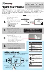
background image

4

BUILT-IN CLOCK

The Vision 25C & 30C incorporate a built-in digital clock and 
multi-inf mative LCD display.

1.1

The digital clock is pre-programmed with a default heating 

pattern (see table 1 below); however this can be modiied to 

suit individual needs (see 1.4).

Pre-programmed Heating Pattern

Day

am

pm

ON

OFF

ON

OFF

Monday

06:30

08:30

4:30

10:30

Tuesday

06:30

08:30

4:30

10:30

Wednesday

06:30

08:30

4:30

10:30

Thursday

06:30

08:30

4:30

10:30

Friday

06:30

08:30

4:30

10:30

Saturday

08:00

10:00

4:00

11:00

Sunday

08:00

10:00

4:00

11:00

1.2 MODES OF OPERATION

The built-in digital clock has the following modes of operation:
1. AUTO ON / AUTO OFF – where the clock uses the pro-

grammed heating pattern (default or user deined) to switch 

the heating ON & OFF at pre-selected times (see Fig.1).

2. MAN ON – where the clock is set to provide heating con-

stantly ON (in this mode the default or user deined heating 

pattern is ignored).

3.  MAN OFF – where clock is set to have the heating constan-

tly OFF (in this mode the default or user deined heating 

pattern is ignored).

4. ADVANCE ON – where the pre-programmed heating pat-

tern is advanced to the next ON period (this function can 
only be used when the clock is in the AUTO OFF mode)

5.  ADVANCE OFF - where the pre-programmed heating pat-

tern is advanced to the next OFF period (this function can 
only be used when the clock is in the AUTO ON mode).

1.3 SETTING THE TIME AND DAY

Ensure that the boiler is electrically supplied.

1. Press and hold the 

 clock button for 3-seconds; the 

right hand digits (minutes) will lash continuously.

2.  Press the 

 up arrow button to increase the minutes va-

lue or press the 

 down arrow button to decrease the 

value.

3.  Once the correct minutes value is displayed, press the 


clock button to store this setting and move to the hours 
value.

4.  Press the 

 up arrow button to increase the hours value 

or press the 

 down arrow button to decrease the value.

5. Once the correct hours value is displayed press the 


clock button to store this setting and move to the day of 
week value.

6.  Press the 

 up arrow button to move forward to the cor-

rect day of week (1 = Monday – 7 = Sunday)or press the 

 down arrow button to move back to the correct day of 

week..

7. Once the correct day of week is displayed press the 


clock button to store this setting and complete the time / 
day of week, setting procedure.

NOTE, the time of day is shown on the display, and is also 

indicated on the 24-segmented display as a lashing segment.

1.4 CHANGING THE HEATING PATTERN

The built-in clock is pre-programmed with a default heating 
pattern (see Fig.1), however this can be changed to a user 

deined heating pattern.

To insert a new heating pattern or change and existing one, 
proceed as follows:

1.  Press and hold the 

 program button for 3-seconds

2.  The day of week segment lashes to indicate which day of 

week is being programmed

3. Use the 

 up arrow button to select the required ON 

periods and use the 

 down arrow button to select the 

OFF periods

NOTE, each segment represents 30-minutes, the large seg-
ments are hour indicators, and the small segments are half-
hour indicators.

4.  When the ON and OFF selections have been made for the 

particular day (relevant day of week is displayed by the 

appropriate number 1 to 7) press the 

 program button 

to store the new settings and move to the next day.

NOTE
If you want to duplicate the new settings for subsequent days, 
e.g. same heating pattern for Monday to Friday, press and 

hold the 

 program button for 3-seconds each time the ap-

propriate day of week is displayed.

EXAMPLE
Day of week = 1 (Monday) Insert the new ON & OFF settings 

(step 3 above), press the 

 button, day of week now shows 

2 (Tuesday).  Press the 

 button for 3-seconds, Monday’s 

settings are now duplicated for Tuesday; repeat as required.   

5.  If you require to change the settings for subsequent days, 

repeat steps 3 & 4 above

6.  Once programming has been completed, continue to press 

and release the 

 program button until you exit the pro-

gramming function (normal display is resumed).

1.5 ADVANCE FUNCTION

When the clock is in the AUTO ON or AUTO OFF mode, it’s 
possible to advance the current setting (ON or OFF) to the 
next programmed setting (ON or OFF), e.g. if the clock is in 
AUTO OFF mode it’s possible to advance to the next AUTO 
ON setting.

1.5.1 ADVANCE ON

Press and hold the 

 up arrow button for 3-seconds, the 

display changes from AUTO OFF to AUTO ON and the 


icon is displayed.

NOTE, the ADVANCE ON function can be cancelled by mo-

mentarily pressing the 

 button.

NOTE, when the ADVANCE ON function is enabled, the hea-
ting will remain ON until the next scheduled OFF period.

1.5.2 ADVANCE OFF

Press and hold the 

 down arrow button for 3-seconds, the 

display changes from AUTO ON to AUTO OFF and the 


icon is displayed.

NOTE, the ADVANCE OFF function can be cancelled by mo-

mentarily pressing the 

 button.

Table 1

Содержание Vision C

Страница 1: ...ctions THESE INSTRUCTIONS TO BE RETAINED BY USER Vok ra is a licensed member of the Benchmark scheme which aims to improve the standards of installation and commissioning of domestic hot water systems...

Страница 2: ...3A 4 Flue system 13 3A 5 Air supply 14 3A 6 Water circulation 14 3A 7 Electrical supply 14 3A 8 Mounting on a combustible surface 14 3A 9 Timber framed buildings 14 3A 10 Inhibitors 14 3A 11 Showers 1...

Страница 3: ...tically Dear Customer Your Vok ra Vision boiler has been designed to meet and exceed the very latest standards in gas central heating technology and if cared for will give years of reliable use and ef...

Страница 4: ...shows the temperature values Pressure gauge shows the current pressure of your heating system the gauge should be set between 1 and 1 5 BAR When the appliance is oper ating the gauge may rise or fall...

Страница 5: ...ADVANCE ON fun ction is active Displayed when the ADVANCE OFF fun ction is active Displays current minutes past the hour Displays current hour of the day 24 hour clock in 30 minute segments lar ge se...

Страница 6: ...y of week setting procedure NOTE the time of day is shown on the display and is also indicated on the 24 segmented display as a lashing segment 1 4 CHANGING THE HEATING PATTERN The built in clock is p...

Страница 7: ...he programmed heating pattern AUTO ON Heating is in an ON period according to the programmed heating pattern MAN OFF Heating is being controlled manually and is switched constantly OFF MAN ON Heating...

Страница 8: ...ow a period of at least two minutes before re setting the appliance 2 6 EXPLANATION OF FEATURES Although the Vok ra Vision has been designed for simplicity of use it utilises the latest in boiler tech...

Страница 9: ...r A01 Ignition failure lame not sensed internal fault Final Reset check appliance operation A02 Limit thermostat fault Final Reset check appliance operation A03 Fan tacho signal fault Final Reset chec...

Страница 10: ...on open vented systems This booklet is an integral part of the appliance It is therefore necessary to ensure that the booklet is handed to the person responsible for the property in which the applianc...

Страница 11: ...nd the boiler will perform a three minute anti cycle timer delay When the request for heat has been satisied the appliance pump and fan may continue to operate to dissipate any residual heat within th...

Страница 12: ...mum system volume 74 litres Pre charge pressure 1 bar 2 5 Dimensions Vision 25C Vision 30C Height mm 715 Width mm 405 Depth mm 248 Dry weight kg 27 28 2 6 Clearances Vision 25C Vision 30C Sides 12mm T...

Страница 13: ...to the roof lashing As determined by the ixed collar of the vertical terminal R To the side of a boundary 300 mm S To the side of an opening or window on a pitched roof 600 mm T Below an opening or w...

Страница 14: ...ansion vessel to accom modate the increased volume of water when the system is heated It can accept up to 8 litres of expansion from within the system generally this is suficient however if the system...

Страница 15: ...itted on a wall of combustible mate rial there is no requirement for a sheet of ireproof material to protect the wall 3 9 TIMBER FRAMED BUILDINGS If the appliance is to be itted in a timber framed bu...

Страница 16: ...An alternative method of illing the system would be from an independent make up vessel or tank mounted in a position at least 1 metre above the highest point in the system and at least 5 metres above...

Страница 17: ...plane see2 9 Areductionmustalsobemadetothemaximumlength see table below when additional bends are used Reduction for additional bends Bend Reduction in maximum lue length for each bend 45 bend 1 3 me...

Страница 18: ...REAR FLUE ig 15 rear lue outlet only Using the template provided mark and drill a 125mm hole for the passage of the lue pipe The hole should be drilled LEVEL to ensure any condense luid that forms is...

Страница 19: ...ired number of lue extensions or bends up to the maximum equivalent lue length between the boiler and vertical lue assembly see ig 14 Ensure that any horizontal sections of the lue system have a minim...

Страница 20: ...e kit for termination The horizontal terminal is supplied with a built in converter box and cannot be shortened A 130mm hole is required for the passage of the concentric terminal through the wall The...

Страница 21: ...ad can be used for connection to the electrical supply Connect the ly lead to a fused plug or fused isolator in the following way brown wire to LIVE supply blue wire to NEUTRAL supply green yellow to...

Страница 22: ...ectrical supply to the appliance is switched on Ensure any external controls are switched to an ON position and are calling for heat Move the selector switch to the ON position the appliance will now...

Страница 23: ...LY AND IS PROPERLY SECURED ENSURE ALL PIPE WORK IS RE CHECKED FOR TIGHT NESS RE FIT APPLIANCE CASING COMPLETE BENCHMARK CHECKLIST FOR UK ONLY Complete details of the boiler controls installation and c...

Страница 24: ...n the reverse order 6 7 LOWER AUTOMATIC AIR RELEASE VALVE ig 28 Carry out component removal procedure as described in 6 4 Remove the expansion pipe locking pin B from the pump as sembly and remove the...

Страница 25: ...dition taking care to Fig 34 6 13 ELECTRODES ig 34 Carry out component removal procedure as described in 6 4 Remove the air chamber front cover Disconnect the electrode leads and ancillary wiring from...

Страница 26: ...removal procedure as described in 6 4 Remove the locking pin Q1 that secures the cover R1 to the hydraulic manifold Using a hooked piece of wire carefully withdraw the by pass cartridge S1 and or DHW...

Страница 27: ...unscrew the inlet connection Unscrew the nut E2 Lift the DHW low switch housing from its seating If necessary remove the locking pin F2 from the DHW low switch taking care not to lose the loat contain...

Страница 28: ...ow 35 C and 55 C respectively the boiler will ire on minimum 25 power until the primary thermistor exceeds 55 C Thereafter the pump will over run for a period of 30 seconds 7 2 3 HEATING MODE With the...

Страница 29: ...emed as immediately dangerous 7 5 CHECKING THE EXPANSION VESSEL Carry out the component removal procedure as described in 6 4 You must ensure that the boiler is completely drained of water Using a sui...

Страница 30: ...mpletion of any task that required the disconnection and re connection of any electrical wiring or component these checks must be repeated 7 8 FAULT FINDING Before attempting any faultinding the elect...

Страница 31: ...ressed in hundreds e g 25 2 500 rpm GAS VALVE CALIBRATION Connect the boiler to the power supply Open the gas tap Set the function selector to OFF RESET monitor off Remove the screws E remove the casi...

Страница 32: ...st the temperature of the heating system indirectly by changing the required room temperature from between 15 C 25 C this will allow the PCB to recalculate the system temperature required the default...

Страница 33: ...controls manufacturer and or Vok ra technical department should you require more speciic information on the suitability of a particular control Further guidance on the recom mended practice for the in...

Страница 34: ...ssure switch S E Spark electrode TSC2 Ignition transformer 3W 3 way motor F O H T Flow over heat thermostat FS Flue sensor FT Flow thermistor NTC RS Return thermistor NTC brown CN3 blue F Hv 1 2 7 1 C...

Страница 35: ...HE APPLIANCE GAS TYPE To convert the appliance to another gas type it is necessary to change the injector and adjust the gas valve CO2 To change the injector see 6 12 1 Toreplacethelangeonthesilencer...

Страница 36: ...7 3 However if the CO2 reading is incorrect the minimum gas pressure must be adjusted as follows locate the minimum adjustment screw ig 44 using a suit able screwdriver remove the protection plug usi...

Страница 37: ......

Страница 38: ...36...

Страница 39: ...38...

Страница 40: ...ies vokera co uk www vokera co uk www vokera ie Sales General Enquires T 0844 391 0999 F 0844 391 0998 Vok ra Ireland West Court Callan Co Kilkenny T 056 7755057 F 056 7755060 Vok ra Limited reserve t...

Отзывы: