background image

VMAC 

– Vehicle Mounted Air Compressors


Toll Free:


1-800-738-8622 Local: 1-250-740-3200 

Fax: 1-250-740-3201 

20 


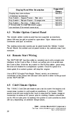
Display Panel Wire Description 

Suggested 

Gauge 

Display box connections  
(4 terminal connector) 

18AWG 

Key Switch 

– Supply Power – Red wire 

14AWG 

Key Switch 

– Return Power – Orange wire 

14AWG 

Key Switch 

– Run key – Yellow wire 

18AWG 

PTO/GENSET/COMPRESSOR switch 
connections (5 terminal connector) 

18AWG 


4.3


Welder Option Control Panel 

 
The remote welder control panel has two supplied connections 
(about 8ft max length) required for operation: 14pin ribbon-cable 
connector and 2pin connector.  
 
The mating connection points are located inside the Welder Control 
Panel. Mount the welder control panel inside a dry cabinet away from 
moisture.  
 

4.4


Remote Start Wiring 

 
The RAPTAIR MF has the ability to remotely start with a single wire 
interface to the Control Box. A blunt-cut yellow wire is located near 
the Control Box. With the key-switch in the RUN position, grounding 
the wire will enable the compressor system. Once the ground is 
interrupted, the control system will stop the engine. 
 
Use a SPST (Single Pole Single Throw) switch, one terminal 
connected to the yellow remote-start wire and the other to the ground 
on the RAPTAIR MF. 


4.5


Cold Climate Option 

The 110VAC Cold Climate heaters are used to warm the engine and 
compressor system in cold weather conditions. A minimum 700W 
power inverter connected to the truck is required for heater usage or 
connected to external AC power prior to starting. Heaters should be 
run for 90 minutes prior to starting the system in cold conditions (time 
will vary depending on ambient temperature).  

Содержание RAPTAIR-MF D600007

Страница 1: ...S y s t e m D 6 0 0 0 0 7 w w w v ma c a i r c o m R A P T A I R MFMU L T I F U N C T I O N A I RC O MP R E S S O R I N S T A L L A T I O NMA N U A L COM P ACT POW E RF UL...

Страница 2: ......

Страница 3: ...Drive Compressor System 16 4 0 Electrical Connections 19 4 1 LED Beacon Module Connection 19 4 2 Display Panel Assembly Connections 19 4 3 Welder Option Control Panel 20 4 4 Remote Start Wiring 20 4...

Страница 4: ...1 Compressor Servicing and Maintenance Schedule 43 8 2 Checking and Adding Compressor Oil 44 8 3 Replacing the Air Filter 45 8 4 Replacing Compressor Oil and Filter 47 8 5 Replacing the Coalescing Fil...

Страница 5: ...l training knowledge and experience Follow all safety precautions for mechanical work If you have difficulty with the installation contact VMAC The VMAC warranty form is located at the back of this ma...

Страница 6: ...r any subsequent warranty claim to be considered valid 1 3 Important Safety Notice The information contained in this manual is based on sound engineering principles research extensive field experience...

Страница 7: ...35 55 80 110 170 280 Newton meter N m 12 24 47 74 108 149 230 379 STANDARD GRADE 8 NATIONAL FINE THREAD Size 3 8 7 16 1 2 5 8 Foot pounds ft lb 40 60 90 180 320 Newton meter N m 54 81 122 244 434 MET...

Страница 8: ...the equipment Always use genuine VMAC replacement parts do not use any substitutes The procedures described in this service manual are effective methods of service and repair Some procedures may requ...

Страница 9: ...perating the compressor Constant vigilance is necessary around high energy equipment Be attentive for unexplained changes in operation parameters and record any changes Never bypass or disable the tem...

Страница 10: ...serious injury or death Never perform maintenance procedures on the system until the compressor has been shut down for at least 5 minutes to ensure the system is fully depressurized After 5 minutes op...

Страница 11: ...grounded when operating the unit Ground using a Green 10AWG AC rated wire to a minimum 3 8th inch post The RAPTAIR MF Multifunction Diesel Drive has an external ground post near the fuel lines The gen...

Страница 12: ...point to ensure that the generator frequency is maintained within the acceptable range PTO loads are not controlled or directly monitored Air pressure in the reservoir tank is maintained when compress...

Страница 13: ...eaker Two of the legs go through a 20 A breaker and to 120V GFCI receptacles found on the panel of the generator One leg goes to a 240V 30A plug There is also a 3 phase plug that is capable of transmi...

Страница 14: ...s is able to power up to a 20HP load through a serpentine belt and a 12V clutch Typically this is fitted with a hydraulic pump and is customizable to your individual needs Equipment connected to this...

Страница 15: ...oved Protected from excessive exposure to the elements and possible incidental damage from other operations Away from heat sources such as engines exhaust systems or other components that generate hea...

Страница 16: ...desirable operation 2 2 Ventilation Requirements During operation the RAPTAIR MF can develop considerable heat Proper ventilation is vital for proper operation and to avoid damage to components Ensure...

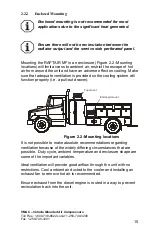
Страница 17: ...erse effect on cooling Make sure that adequate ventilation is provided so the cooling system will function properly i e a pull out drawer Top mount Enclosed mount Figure 2 2 Mounting locations It is n...

Страница 18: ...1 2 12 mm bolts Use bolts washers and locknuts or Loctite Connect a ground wire to the ground terminal found on the bottom of the generator side of the unit beside the air outlet Ensure this is conne...

Страница 19: ...uidelines Ensure any hoses or wires attached to PTO equipment are routed away from sharp edges or hot surfaces 3 1 2 Optional Fuel tank installation The fuel tank will be installed on the generator si...

Страница 20: ...is located below the diesel drive unit a fuel priming pump is recommended in the supply line When plumbing into a truck diesel supply avoid connecting the RAPTAIR MF fuel supply to the lowest point o...

Страница 21: ...To fully utilize the features of the RAPTAIR MF the display panel with the key switch and display box should be mounted in a convenient location for the operator Mount the Display Panel inside the cab...

Страница 22: ...ay from moisture 4 4 Remote Start Wiring The RAPTAIR MF has the ability to remotely start with a single wire interface to the Control Box A blunt cut yellow wire is located near the Control Box With t...

Страница 23: ...reme cold weather Connections should be made to the external battery at the battery terminals The diesel drive will charge the vehicle batteries while running While the RAPTAIR MF is in the STANDBY st...

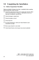
Страница 24: ...TAIR MF for the first time Check the compressor oil level The compressor has been filled to the correct level prior to shipping Note that the oil is very clear and it is difficult to see the level Che...

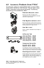
Страница 25: ...nd dirt from the air stream Adds atomized tool oil to lubricate tools Reduces pressure for longer tool life Hose Reel A700007 Secure compact retractable hose storage in a sturdy reel Air Receiver Tank...

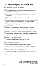
Страница 26: ...e Multiple adjustable system parameters for delays pressures and restart options Monitoring the compressor engine coolant and manifold temperature probe connection and temperature range Monitoring air...

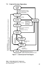
Страница 27: ...Engine Restart is enabled or Air pressure below Restart Pressure STANDBY delay reached UNLOAD delay reached Engine and Compressor at temperature greater than 5 C 41 F ON ENTER Button Pushed Remote ena...

Страница 28: ...for 3 seconds before going into the next state to crank the engine The glow plugs are enabled during the buzzer cycle and during engine cranking Temperature Glow Plug Delay Less than 20 C 68 F 15 sec...

Страница 29: ...Pressure the Delay to Unload timer will start counting down Once the timer reaches the delay time the system will switch to the UNLOAD state If air pressure drops below System Pressure minus Top up Pr...

Страница 30: ...e air use rate is above a preset value HIGH AIR USE RATE the system will detect that an air tool is used and will switch states The system will also return to the RUNNING state if pressure is below th...

Страница 31: ...it detects engine or compressor temperature is below 5 C 23 F As with many settings this can be disabled through the Control Box The Disable Auto Restart Delay setting will prevent the system from res...

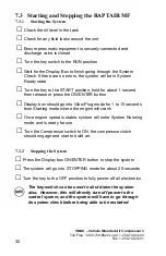
Страница 32: ...d then release or press the ON ENTER button Display box should go into Glow Plug mode for 1 to 15 seconds then Starting mode where the engine will crank Once engine speed is stable system will enter S...

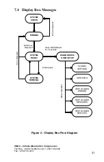
Страница 33: ...lay Box Messages No Errors Detected Press NEXT BACK for 5 seconds SYSTEM CHECK SYSTEM RUNNING DIAGNOSTICS USER SETUP SYSTEM READY Errors Cleared ERRORS SYSTEM SETTINGS SERVICING VIEW LOGGED ERRORS VIE...

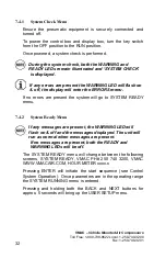
Страница 34: ...enter the ERRORS menu If no errors are present the system will go to SYSTEM READY menu 7 4 2 System Ready Menu If any messages are present the WARNING LED will flash on off and the messages displayed...

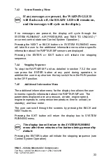
Страница 35: ...g Sequence To stop the RAPTAIR MF unit as detailed in section 7 3 2 the user can press the ENTER button at any point during operation in addition the user may also turn the key switch from the RUN pos...

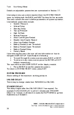
Страница 36: ...er Threshold Battery Restart Upper Threshold Battery Restart Delay Factory Reset Upon entering this menu the user will see information on how to navigate USER SETUP Specifically the following To scrol...

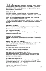
Страница 37: ...the system RESTART PRESSURE This parameter is used to restart the system when pressure has gone below the set value in STANDBY COLD ENGINE RESTART This will allow the engine to restart if temperature...

Страница 38: ...3200 Fax 1 250 740 3201 36 FACTORY RESET All adjustable parameters will reset to factory settings Pressing ENTER on this screen will display CANCEL Pressing NEXT will show CONFIRM RESET Pressing BACK...

Страница 39: ...illuminate when the RAPTAIR MF is in STANDBY mode and is able to restart when air use is detected The buzzer module will enable and alert the operator before the engine starts The system may automati...

Страница 40: ...PRESSURE xxx x PSI If the previous error is present the air pressure is displayed 34 ENGINE RPM NOT DETECTED Engine RPM is not detected Wire may be cut tach sensor on bell housing may be loose or fue...

Страница 41: ...ll show up 10 hours before the 200 hour service internal 54 COMPRESSOR SERV 200HR 6MTH The system is due for a service This warning will show after every 200 hours of running the compressor Clearing t...

Страница 42: ...t point for pressure based restart condition 0 to 30PSI 0 5PSI increments 3 0PSI sec Pressure Restart PSI Air pressure set point for pressure based restart 80 to 150PSI 5PSI increments 120PSI Allow Co...

Страница 43: ...s the ON ENTER button or turn the key to the START position The Display box will display GLOW PLUG mode on the screen and delay starting the engine from 1 to 15 seconds depending on the engine tempera...

Страница 44: ...f service and inspection procedures together with cleaning A well planned maintenance program lowers maintenance costs reduces down time and can prevent possible accidents due to failed components Fig...

Страница 45: ...to assure good performance and long service life The hours indicated are those displayed on the compressor hour meter Service should be performed at the lesser of the two intervals whichever occurs fi...

Страница 46: ...ut 0 5 litres of oil Check the level the oil has reached on the oil level sight glass MAX ADD UP Sight Glass Window Drain Plug VR70 Figure 4 Checking Compressor Oil Level Use a funnel inserted into th...

Страница 47: ...e replaced Never clean the filter element with compressed air as this will allow some contaminates into the compressor system Always replace the air filter element Remove the filter element from the f...

Страница 48: ...Filter Retainer Remove the masking tape or cloth from the compressor air intake The new VMAC filter is oval make sure that the filter fits over the machined step on the intake housing Do not use compr...

Страница 49: ...dripping onto the belt and or battery and drain oil into a container that can hold at least 4 liters of oil Dispose of the oil in accordance with the Environmental Protection Laws in your location Rem...

Страница 50: ...Loctite blue and install it into the Tank base If Compressor Oil Filter Nipple is stuck in Oil Filter remove and Loctite into Tank Base before installing Filter Compressor Oil Filter Compressor Oil Fi...

Страница 51: ...ighten the filter as this may damage the seal or filter Follow the oil level checking procedure in Section 8 2 1 8 5 Replacing the Coalescing Filter Follow all safety precautions COALESCING FILTER Do...

Страница 52: ...rifice on the bottom of the scavenge tube on the lip of the coalescing filter This scavenge screen orifice is attached to the scavenge tube by a push to connect fitting if the fitting has come off of...

Страница 53: ...er onto the threaded nipple until the gasket contacts the sealing surface of the manifold block Tighten the filter an additional 3 4 to 1 turn to seat the sealing gasket Never over tighten the filter...

Страница 54: ...d compressor servicing is due Refer to Section 7 6 2 for the Display box servicing message list Engine service reminders do not need to be cleared in the Display Box Reminders will show 10 hours befor...

Страница 55: ...he key switch to the RUN position do not start the unit Enter Diagnostics mode in the Display Box by holding the NEXT and BACK button for 5 seconds Use the NEXT button to scroll to the Servicing secti...

Страница 56: ...anding how the system operates Isolating the potential causes by accurate testing using the correct recognized procedures Performing proper repairs using the correct procedures outlined in this manual...

Страница 57: ...Check for kinked or pinched lines Plugged oil filter Replace oil filter Cooler not functioning or plugged Replace or clean oil cooler Engine cooling system failure high engine temperature Correct prob...

Страница 58: ...6 10 0 Warranty 10 1 Maintenance and Repair Records System Installation System ID number Compressor Serial Number System Installed by Address Date Installed 50 Hour Inspection Date Performed by Addres...

Страница 59: ...50 740 3200 Fax 1 250 740 3201 57 400 Hour or 12 month service Date Performed by Address Parts replaced or notes 600 Hour or 18 month service Date Performed by Address Parts replaced or notes 800 Hour...

Страница 60: ...00 Fax 1 250 740 3201 58 10 2 Part Replacement or Adjustment Record Record 1 Date Performed by Part or Adjustment Reason Record 2 Date Performed by Part or Adjustment Reason Record 3 Date Performed by...

Страница 61: ...622 Local 1 250 740 3200 Fax 1 250 740 3201 59 Record 5 Date Performed by Part or Adjustment Reason Record 6 Date Performed by Part or Adjustment Reason Record 7 Date Performed by Part or Adjustment R...

Страница 62: ...This page intentionally left blank...

Страница 63: ...ny Name _____________________________________ City _____________________ State Province ______________ Installation Date _____ _____ _____ Day Month Year Owner Information Company Name _______________...

Страница 64: ...This page intentionally left blank...

Страница 65: ...This page intentionally left blank...

Страница 66: ...This page intentionally left blank...

Страница 67: ......

Страница 68: ......

Отзывы: