background image


In the following tables, hydraulic flow can be below 
minimum specifications. These flow ratings are for 
startup only, not for operation of the PREDATAIR. Refer 
to Section 2.3 Hydraulic Requirements for flow 
specifications. 

!


6.2.1 Suction Line Sizing 


!

Failure to select the correct suction line size can result 
in pump cavitation and premature pump failure.  


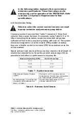
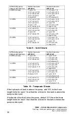
Choose a suction hose size from Table 7 (based on 4 ft/sec fluid 
velocity), then upsize the hose, if necessary, using Table 8, 9 or 10. 
When consulting these tables, locate line sizes that will provide 
sufficient oil flow to the pump during startup with cold oil. The system 
should be designed to run at the lowest GPM possible at startup, 
then use a throttle control to increase GPM for operations once the 
oil has warmed.  

Space and port size issues at the pump may require a short length of 
smaller than desired hose. Keep this as short and as large (ID) as 
possible to limit effect on performance and pump life. 

Maximum Operating  GPM 

Suction Hose Size 

8-13 1” 

14-15 1-1/4” 

16-22 1-1/2” 

Table 7 – Suction hose size 

With tank and Suction Preheat 
system. 
 

Preheat to –20

°

C or warmer prior to 

pump startup.  Suction hose sizing same 
as “Cold Climate” with AW 32 oil. 

No tank preheat.  Line sizing here 
is based on strict adherence to 
Note 1 in Table 1. 

Suction hose sizing same as “Cold 
Climate” with AW 22 oil. 
 

Table 8 – Extreme Cold Climate 


VMAC – Vehicle Mounted Air Compressors


Toll Free:


1-888-241-2289 Local: 1-250-740-3200 

Fax: 1-250-740-3201 

29

Содержание PREDATAIR

Страница 1: ...ng the PREDATAIR 11 3 1 Mounting the Compressor 11 3 2 Connecting the Wiring 12 3 3 Speed Control 13 4 0 Completing the Installation 16 4 1 Before Operation Checklist 16 4 2 After Engaging the Hydraul...

Страница 2: ...if you do not have the appropriate mechanical training knowledge and experience Follow all safety precautions for mechanical work If you have difficulty with the installation contact VMAC The VMAC war...

Страница 3: ...r to the outlet Pressure regulation is achieved with a mechanical inlet control valve and an adjustable pressure regulator The compressor is protected by a paper type replaceable air filter and a spin...

Страница 4: ...scing filter Minimum clearance for servicing 6 inches Compressor oil fill shipped full from the factory Oil level sight glass make sure this can be easily accessed for daily inspection Compressor oil...

Страница 5: ...D GRN PPL RED GRN ORG RED GRN RED WHT ORG PPL PPL ATM MINI 3A VIOLET HYDRAULIC MANIFOLD RED RED ORG WHT BLOWDOWN CAP SYSTEM PRESSURE SENSOR AIR SEPARATOR TANK RED GRN BLK UNLOAD SOLENOID GRN GRN RED G...

Страница 6: ...such as engines exhaust systems or other components that generate heat it is not in a location where it will be exposed to high contamination levels including combustible gases The PREDATAIR60 requir...

Страница 7: ...se undesirable operations 2 2 Ventilation Requirements During operation the PREDATAIR can develop considerable heat as much as a house furnace Proper ventilation is vital for proper operation and to a...

Страница 8: ...uired if the PREDATAIR is mounted in the same enclosure as the hydraulic oil reservoir The heat generated during operation will continue to heat the hydraulic oil even with fresh ambient air entering...

Страница 9: ...with cold oil Compressor capacity depends on hydraulic flow 2 3 1 PREDATAIR60 For single speed operation a minimum of 14 GPM and a maximum of 20 GPM hydraulic oil flow is required For two speed operat...

Страница 10: ...nal of the battery or to a substantial fully grounded point on the vehicle chassis located in an area which will provide a good ground at all times Power should be ignition switched through a relay to...

Страница 11: ...n spaced at 22 inches wide and 14 inches deep Fasten the unit in place using Loctite on the threads A mounting bracket kit A700140 is available Do not mount the unit directly to the body without the r...

Страница 12: ...protected from weather PREDATAIR60 Battery Fuse or circuit breaker 30A PREDATAIR see table 1 for correct wire gauge Red Green Ignition switched relay Figure 7 VMAC Vehicle Mounted Air Compressors Tol...

Страница 13: ...air demand conditions and for a lower engine speed under low air demand conditions Most work trucks either have a built in electrically activated idle up system or an after market product may be avai...

Страница 14: ...t drop below the minimum requirement A flow meter should be temporarily plumbed into the PREDATAIR return line to confirm actual hydraulic flow A load tester with the load valve adjusted to zero can b...

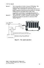
Страница 15: ...the PREDATAIR Figure 9 Speed 2 The purple wire is used to activate a second preset throttle speed that will provide the maximum GPM rating Figure 9 Red Purple Green From PREDATAIR Power circuit Thrott...

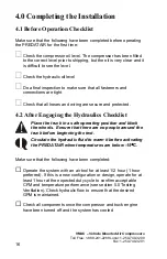
Страница 16: ...and truck engine 1 Before Operation Checklist M the PREDATAIR for the first time C to the correct level prior to shipping but the oil is very clear and it is difficult to see the level C D connection...

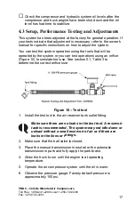
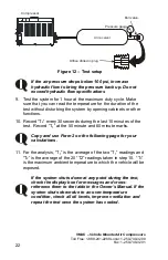
Страница 17: ...to determine the correct orifice size Figure 10 Test tool 1 Install the test tool in the air reservoir tank outlet fitting Make sure there are no leaks in the test tool A reservoir tank is recommende...

Страница 18: ...If the air pressure doesn t drop after approximately another 20 seconds the engine will idle down to the lower speed setting 9 After one minute if the air pressure still hasn t dropped the compressor...

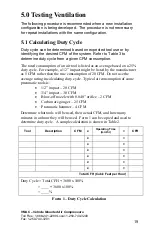
Страница 19: ...d as an average based on a 25 duty cycle For example a 1 2 impact might be listed by the manufacturer as 5 CFM rather than the true consumption of 20 CFM Do not use the average rating in calculating d...

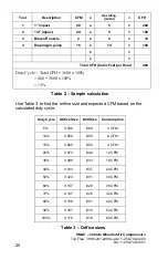
Страница 20: ...t per Hour 460 Duty Cycle Total CFH 3600 x 100 460 3600 x 100 13 Table 2 Sample calculation Use Table 3 to find the orifice size and expected CFM based on the calculated duty cycle Duty Cycle Orifice...

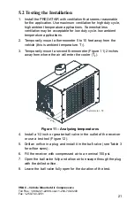
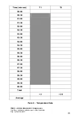
Страница 21: ...Figure 11 2 inches away from where the air will enter the cooler T2 2 Thermometer T2 Figure 11 Analyzing temperatures 4 Install a 1 2 inch or greater ball valve in the outlet of the receiver or use a...

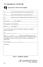
Страница 22: ...1 at the 50 minute and 60 minute marks Copy and use Form 2 on the following page for your calculations 11 For the analysis T1 is the average of the two T1 readings and T2 is the average of the 20 T2 r...

Страница 23: ...1 888 241 2289 Local 1 250 740 3200 Fax 1 250 740 3201 23 Time min sec T1 T2 50 00 50 30 51 00 51 30 52 00 52 30 53 00 53 30 54 00 54 30 55 00 55 30 56 00 56 30 57 00 57 30 58 00 58 30 59 00 59 30 60...

Страница 24: ...e Tmax _______ See Table 4 Tx T3 T2 T1 The expected cooler intake temperature at maximum ambient temperature Tx ___ ___ ___ _____ Tmax _____ Tx ______ If Tmax is greater than or equal to Tx the ventil...

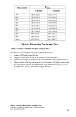
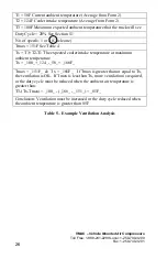
Страница 25: ...7 C 90 89 F 32 C 89 F 32 C 100 85 F 29 C 85 F 29 C Table 4 Determining Temperature TMAX Table 5 shows a sample analysis using Form 3 Measures for correcting inadequate ventilation include reduce GPM a...

Страница 26: ...e Tx _100_ _124_ _58_ _166F_ Tmax _151F_ Tx _166F_ If Tmax is greater than or equal to Tx the ventilation is OK If Tmax is less than Tx more ventilation is required or the duty cycle must be reduced w...

Страница 27: ...ooler 10 No air consumption compressor in standby state hydraulic oil circulating through cooler 6 Brief use of compressed air compressor tops up receiver and unloads 7 No air consumption compressor i...

Страница 28: ...system design guidelines generally call for the following maximum fluid velocities which are then used to select line sizes for any particular GPM suction 4 ft sec return 10 ft sec pressure 20 ft sec...

Страница 29: ...ned to run at the lowest GPM possible at startup then use a throttle control to increase GPM for operations once the oil has warmed Space and port size issues at the pump may require a short length of...

Страница 30: ...1 5 ft 2 up to 3 ft 2 1 2 up to 8 ft 3 above 8 ft Table 9 Cold Climate GPM during pump start up and warm up Suction hose size AW 32oil Suction hose size AW 46 oil 8 GPM or less 1 up to 4 ft 1 1 4 up...

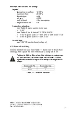
Страница 31: ...0 8 4 conclusion use 1 3 4 ID suction hose or larger 6 2 2 Return Line Sizing Choose a return line size from Table 11 based on 10 ft sec fluid velocity then upsize the line if necessary using Table 12...

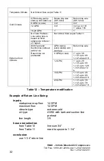
Страница 32: ...Return line size 8 GPM or less 1 up to 3 ft 1 1 4 up to 8 ft 1 1 2 above 8 ft 12 GPM 1 up to 2 ft 1 1 4 up to 5 ft 1 1 2 up to 12 ft 1 3 4 above 12 ft 16 GPM 1 1 4 up to 4 ft 1 1 2 up to 9 ft 1 3 4 ab...

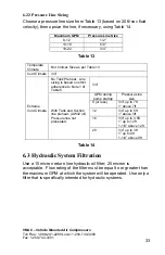
Страница 33: ...strict adherence to Note 1 of Table 5 3 4 GPM during pump startup Pressure Line size 8 or less 3 4 up to 7ft 1 above 7ft 12 3 4 up to 5ft 1 above 5ft 16 3 4 up to 3 5ft 1 up to 12ft 1 1 4 above 12ft...

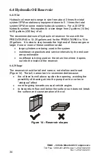
Страница 34: ...large cylinders are being used in the system maintenance practices and service intervals by the end user are questionable no diffuser is being used on the return line where it opens out into the insid...

Страница 35: ...line to the suction line in an S shaped flow when viewed from above to promote cooling contact with walls provide time for deaeration and time for contaminants to drop out They should be notched or h...

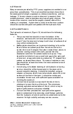
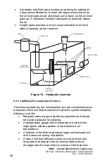
Страница 36: ...mmended Features The following features are not essential but are recommended as measures which will help to maximize hydraulic system reliability efficiency and life Magnetic drain plug s trap ferrou...

Страница 37: ...is not understood and not properly maintained 6 5 Avoiding Cavitation Pump cavitation may occur if the suction at the hydraulic pump inlet exceeds 6 InHg 3psi of vacuum relative to local atmospheric p...

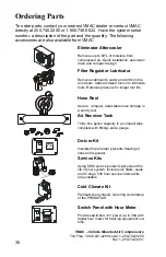
Страница 38: ...Reel Secure compact retractable hose storage in a sturdy reel Air Receiver Tank Thirty five gallon capacity in a compact tank complete with fittings and a gauge DE ICING HEATER De icer Kit Insulated...

Отзывы: