Vivitek D75X ULTRA SHORT SERIES Скачать руководство пользователя страница 3

2

!

WARNING

!

CAUTION

THE LOCATION FOR WALL MOUNTED BRACKET

ABOUT THIS INSTALLATION INSTRUCTION 


If the wall mounted bracket is meant for installation of the projector on walls and the wall should be strong 

enough to hold the projector and wall mounted bracket.


The wall mounted bracket should be installed on concrete walls. The quality of projector and hanger should 

be qualified before installation, and the strength of walls should be verified and maintained. If the strength of 

walls is not strong enough, please strengthen them before installation.


Please test the wall mounted bracket at regular intervals so as to make sure that there are no broken parts or 

loose screws.If any broken part is found, please refrain from using the wall mounted bracket. If the wall mounted 
bracket or projector falls, personal injury or property loss may occur.


Please do not with or modify the wall mounted bracket.


Please do not hang up the wall mounted bracket or hang things on the wall mounted bracket. If the projector or

the wall mounted bracket falls, personal injury or property loss may occur.


Glues lubricant or oil should not be used to wall mounted bracket can chemical attack which could result in a 

rupture of the wall mounted bracket and then cause the projector to fall. As a result, personal injury or property 
loss may occur.


Please tighten all the nuts and screws after adjustment. Otherwise, the projector or hanger may fall and lead to

 personal injury or property lass. 


Please refrain from loosening the nuts and screw after installation, unless otherwise deemed necessary and 

performed by qualified specialists who have technical knowledge and ability.


Please test the wall mounted bracket at a regular interval to ensure the nuts and screw are tight. If the nuts and 

screws are found loose, please tighten them, otherwise, the projector or the wall mounted bracket may fall and cause 

personal injury and property loss.


Please do not install the hanger frame in places where the temperature could be higher than that the projector’s

 maximum sustainable temperature, because the exceeding high temperature may damage the projector.


Please avoid installing the wall mounted bracket in places that is too wet or too dusty so that lens and optical 

components can be protected from being contaminated.


While adjusting wall mounted bracket, please do not employ excessive force because the wall mounted bracket 

may break and cause personal injury.


Only professional person can dismantle or reset the projector (including maintaining and overhauling). Please 

consult the relevant information as illustrated in the instructions.

1

Conducting power routing in advance in the position where the hanger frame is installed.

2

The position should be away from other electrical equipments, such as fluorescent lamps and air condition.Some 

      fluorescent lamps may cause interference signal to the projector’s remote control.

3

The length of connecting power cord should be less than 20 meters so as to reduce noise interference.

4

Plug-in screen or flat screen is suggested.

5

When using interactive function, please make sure to set the projector under the following condition,

     (1)

Projection screen is rectangle in shape with no distortion.

     (2)

The vertical and horizontal angle between projector and the projection screen should be less than 3 degree 

             comparing to the projector screen.
     (3)

The horizontal and vertical keystone correction should be less than 5 degree while using keystone correction,  


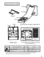
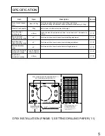
This instruction introduces how to use customized wall mounted bracket to install D75 ultra 

short throw projector on walls. The unit of measurement for all sizes mark place in this instruction 

is in “mm”.

Содержание D75X ULTRA SHORT SERIES

Страница 1: ...D75X ULTRA SHORT SERIES INSTALLATION MANUAL English Edition ...

Страница 2: ...r improper installation may cause wall mounted bracket to fall resulting in personal injury or property damage Please install the wall mounted bracket according to this instruction Otherwise the wall mounted bracket may fall and result in personal injury or an accident Operating power cord with care Improper operation could cause fire or electric shock Please comply with the following requirements...

Страница 3: ... screw are tight If the nuts and screws are found loose please tighten them otherwise the projector or the wall mounted bracket may fall and cause personal injury and property loss Please do not install the hanger frame in places where the temperature could be higher than that the projector s maximum sustainable temperature because the exceeding high temperature may damage the projector Please avo...

Страница 4: ...per position according to the projector distance chart 5 Power cord should pass through the hanger frame 6 Adjust the slider plate up and down to align to the standard position 7 Install the projector onto the hanger frame 8 Connect the power cord and other electrical cables to the projector 1 Switch on the projector 2 Adjust the aspect ratio 3 Display the test image 4 Adjust the left and right al...

Страница 5: ... 2337 2413 2464 2286 2210 2159 11 59 321 5 11 82 12 16 12 38 12 72 12 95 327 4 336 1 341 6 350 2 356 1 82 85 80 77 75 2083 2159 2032 1956 1905 12 88 354 4 13 18 13 60 13 90 14 32 361 4 372 6 380 2 390 9 68 1727 11 86 328 5 78 1987 13 18 362 80 2032 11 02 307 2 100 2540 13 26 364 1 Screen size inch mm diagonal inch mm H1 Vertical distance Screen size inch mm diagonal inch mm H1 Vertical distance S ...

Страница 6: ...nt by range Up and down adjustment by range D75X ULTRA SHORT SERIES BRACKET 1 SETTING DRILLING PAPER 1 1 H1 VERTICAL DISTANCE THE DISTANCE FROM PROJECTED SCREEN TO THIS PART 114 85 A 4 X A Ø8 5 THREAD WITH DEPTH 60MM A A A 92 95 97 D755WT WXGA 0 35 90 87 85 2337 2413 2464 2286 2210 2159 11 59 321 5 11 82 12 16 12 38 12 72 12 95 327 4 336 1 341 6 350 2 356 1 82 85 80 77 75 2083 2159 2032 1956 1905 ...

Страница 7: ...6 SCREEN D H1 SCREENSHOT OF PROJECT DISTANCE 27 2 ...

Страница 8: ... 72 12 95 327 4 336 1 341 6 350 2 356 1 82 85 D751ST XGA 0 43 Screen size diagonal Screen width Screen height inch mm inch mm inch mm inch mm inch mm 80 77 75 2083 2159 2032 1956 1905 65 67 63 61 59 1666 1727 1626 1565 1524 49 51 48 46 45 1250 1295 1219 1173 1143 Projecting distance D Vertical distance H1 13 83 351 4 14 62 15 72 16 51 17 61 371 4 399 4 419 4 447 4 12 88 354 4 13 18 13 60 13 90 14 ...

Страница 9: ...ails please refer to P 9 Perforate the setting wall percussion drill and drill 8 5 60mm depth Step 2 Install M8 70 setscrew in the wall s hole Step 3 Use M8 70 setscrew 4X fix structure frame 1 to the wall s hole Step 4 Install structure frame 2 on structure frame 1 see P 10 switch it to intermediate position and use screw B M4 10 up and down adjusting fixing screw to lock it yet Step 5 Loosen scr...

Страница 10: ...alue H1 according to the projector distance chart 2 Use D79X setting perforating paper of ultra short throw series 1 1 to determine the corresponding vertical distance H2 H1 27 2mm 3 Fix the D79X setting perforating paper of ultra short throw series 1 1 and drill the wall according to the hole position on paper see picture 1 4 Drive the attached setscrew 4 M8 70mm in the corresponding wall s hole ...

Страница 11: ...N Installing steps of structure frame 2 1 Place structure frame 2 s neck into structure frame 1 s up and down adjusting screw inserts 2 Screw B screw M4 10mm into structure frame 1 s corresponding threaded hole slightly 2 PCS of both left and right side 3 Use up and down adjusting screw to adjust structure frame 2 to proper position and tighten the screw B 4 M4 10mm ...

Страница 12: ...EENSHOT 1 SCREENSHOT 2 Installing steps of structure frame 2 1 Loosen C screw 2 M4 10mm 2 Decline the three axis fine tuner by 5 degree to aim at the registration mast As illustrated in the following picture 2 install the slide way on structure frame 2 s slide way and switch it to intermediate position 3 Tighten screw C 2 M4 10mm into structure frame 2 s corresponding threaded hole slightly do not...

Страница 13: ...en screw H 4X M4 10 and remove structure frame 7 2 Use I screw 3 M4 10mm to connect structure frame 7 and projector and assemble them together 3 Assemble the connected structure frame 7 and projector on structure frame 6 4 Tighten screw H 4 M4 10mm into structure frame 6 s corresponding threaded hole slightly not locked 5 Slide structure frame 7 to proper position and tighten screw H 4 M4 10mm ...

Страница 14: ... STEP 1 Instruction of left and right adjusting movement 1 Loosen screw C 2 M4 10mm slightly 2 Push structure frame 3 left or right directly to conduct adjustment 3 Adjust screw C to the proper position X axis direction and lock it 2 M4 10mm 4 The maximum adjustable distance is 30mm ...

Страница 15: ...ement 1 Tuner E does clockwise movements and its function is to adjust structure frame 6 to drive projector into clockwise X axis direction rotation adjustment picture A 2 Tuner E does anti clockwise movements and its function is to adjust structure frame 6 to drive projector into anti clockwise X axis direction rotation adjustment picture B 3 The maximum adjustable angle is 5 degree ...

Страница 16: ...otate axis nut slightly 2 Take the rotation axis as the axis Z axis adjust the setting disc through horizontal left and right rotation so that structure frame 7 can drive projector towards horizontal rotation Z axis direction 3 When the horizontal rotation position is adjusted to a proper position tighten the screw F 4 When the three axis are adjusted to proper positions tighten the rotation axis ...

Страница 17: ...does clockwise movements and it s function is to move structure frame 6 to drive projector towards a clockwise Y axis direction rotation adjustment picture D 2 Tuner G does anti clockwise movements and it s function is to move structure frame 6 drive projector towards an anti clockwise Y axis direction rotation adjustment picture C 3 The maximum adjustable angle is 5 degree ...

Страница 18: ...P 5 Instruction of image size adjustment movement 1 Loosen screw D 4 M4 10mm slightly Move structure frame 5 forward and backward to adjust its position in Y axis 2 For the distance between screen and projector please refer to the projector sheet P 7 3 When the image size is OK please tighten screw D 4 M4 10mm 4 The maximum adjustable distance is 120mm ...

Страница 19: ...crew to make sliding structure frame 2 up and down so as to adjust the image position up and down Z axis direction 2 Please refer to the projector distance sheet P 7 for the highest position of screen to the projector s up and down distance H1 3 When the image up and down position is well adjusted tighten screw B 4 M4 10mm 4 The maximum adjustable distance is 40mm AFTER ALL THE ADJUSTMENT PLEASE T...

Страница 20: ...ip code 200120 Tel 86 21 58360088 Fax 86 21 58360099 http www vivitek com cn Vivitek EMEA Zandsteen 15 2132MZ Hoofddorp The Netherlands Tel 31 20 655 0960 Fax 31 20 655 0999 E mail info vivitek eu Web www vivitek eu D79X ultra short series installation instructions 2nd Edition Service ...

Отзывы: