4
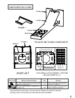
TRI-AXIS FINE-TUNING COMPONENTS
PART LIST
FRAME 7
HARDWARES INCLUDED
Screen shot
Hardware Specifications
Qty
Purpose
3 (pcs)
4 (pcs)
FRAME 3
FRAME 4
FRAME 5
FRAME 6
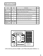
D75X INSTALLATION (FRAME 1) SETTING
DRILLING PAPER (1:1)
M4*10mm ball head cross head screw (with flat
gasket and spring washer)
M8*70mm setscrew (with nut, flat gasket and
spring washer)
Used for connecting wall mounted bracket
structure # 7 with projector
Used for installing and fixing wall mounted
bracket structure #1 onto the wall
D75X
ULTRA SHORT SERIES (BRACKET 1)
SETTING DRILLING PAPER (1:1)
H1 VERTICAL DISTANCE
(THE DISTANCE FROM
PROJECTED SCREEN
TO THIS PART)
114
85
A
4
X
A- 8.5
THREAD
WITH DEPTH 60MM
A
A
A
92
95
97
D755WT WXGA 0.35
90
87
85
2337
2413
2464
2286
2210
2159
11.59
321.5
11.82
12.16
12.38
12.72
12.95
327.4
336.1
341.6
350.2
356.1
82
85
80
77
75
2083
2159
2032
1956
1905
12.88
354.4
13.18
13.60
13.90
14.32
361.4
372.6
380.2
390.9
68
1727
11.86
328.5
78
1987
13.18
362
80
2032
11.02
307.2
100
2540
13.26
364.1
Screen size
inch
mm(diagonal)
inch
mm
H1 Vertical distance
Screen size
inch
mm(diagonal)
inch
mm
H1 Vertical distance
S/N
4
5
6
7
3
2
1
S/N
4
5
6
7
3
2
1
D751ST XGA 0.43
8
TOP
IT
MUST
ALIGN CENTER OF SCREEN
CENTRAL LINE WHEN INSTALLING
Description:
1.“A” is the drill location. Please
review the description in manual
page 9.
2.This screenshot is only for D751ST
XGA 0.43/D WXGA 0.35 hanger.
3.The scale in the screenshot for all
indicated location is 1:1.
FRAME 2
FRAME 1
1:Please follow the instructions in the manual and install with the attached hardwares.
2:Please prepare the required tools and hardwares before installation


