User Guide
VTouch-Plus Configuration Tool
VITREA Smart Home Technologies | T: +972.3.5474746 | F: +972.3.5474738 | vitrea-sh.com |
Page
11
of
27
The following describes the VP Gateway connections:
USB Port
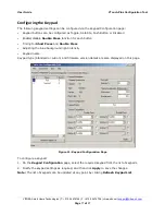
– The PC is connected to the USB port to configure the keypads via a utility software
or terminal emulation program. The following functions are available via the USB port:
Assign addresses to the keypads
Add/delete/replace keypads in the system
Set the Button-Type for each button according to application requirements
Set the intensity level of the surrounding blue LEDs
Set the timing parameters of each keypad for “short-press” and “double-press”
Give a name/location to each keypad in the system
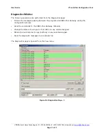
Test communication with each keypad
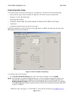
Select RS-232 or IP connectivity to the Host
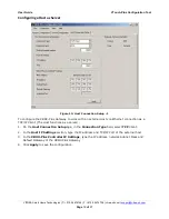
Set the IP parameters.
RS-232 Port
– The VP Gateway can connect to the Host via this port. The connector is a DB-9
female and only 3 wires are used for communication: Pin 2 is the TX of the VP Gateway, Pin 3 is
the RX of the VP Gateway, and Pin 5 is GND.
Pin 2 connects to the RX of the Host.
Pin 3 connects to the TX of the Host.
Pin 5 connects to the GND of the Host.
The communication parameters are: 9600, N, 1.
Note
: When the VP Gateway is configured to communicate with the Host via the RS-232 port,
the IP port is disabled.
IP Port
- The VP Gateway can connect to the Host via this port.
Note
: When the VP Gateway is configured to communicate with the Host via the IP port, the RS-
232 port is disabled.
RS-485 Port
– The VP Gateway communicates with the VTouch Plus keypads via this port. Pins
A and B are connected via the 4-wire bus to Pins A and B of each keypad (A to A and B to B).
Term
– When a termination is required, a jumper is connected to the Term connector. An
internal 120 Ohm resistor will terminate the communication line.
24 VDC
– This is connected to the (+) and (-) terminals of the 24 VDC power supply and to the
two power wires of the 4-wire bus.
LED Indications
– There are three LEDs on the top panel of the VP Gateway:
Power
– Indicates that the 24 VDC is connected.
Error
– Lights up when there is a communication problem between the VP Gateway and at
least one of the VTouch Plus keypads.
Data
– Blinks when there is communication between the VP Gateway and the Host.


