background image


Page 11

HDR-1000 User and Technical Manual

Web Browser Control Interface 

The HDR-1000 has on-board fi rmware that enables web browser control without the 
need to install software. 

To set-up PC control of your receiver, complete the following steps:

1. 

Connect an Ethernet cable to the NETWORK connector on your HDR-1000 and to 
your Windows PC.

2. 

Open a web browser on your PC and type 

192.168.1.100

 into the URL address 

fi eld and press 

Enter

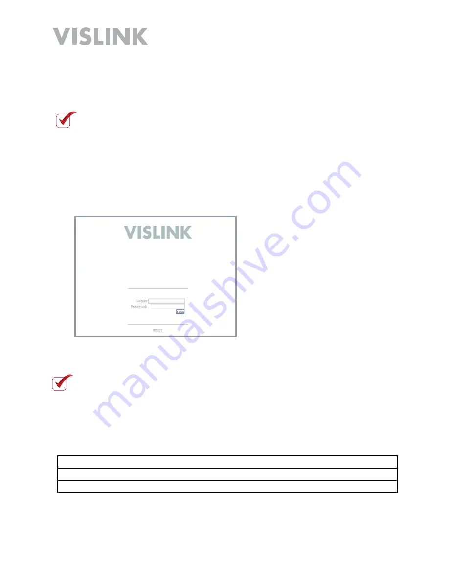
. The login screen displays.

3. 

Enter your user name and password then click the 

Login

 button. 


NOTE

The receiver is factory programmed with the user name root and  


password root. To avoid unauthorized access, the factory assigned password  


should be changed by accessing the System > Change Password tab. See   


Change Password section.

root
root


NOTE

You must complete the PC Network Setup section before proceeding.

Write down your password information here.

Login
Password
Unit S/N

Содержание HDR-1000

Страница 1: ...KAMELYON Series HDR 1000 Compact HD SD Digital Video Receiver User and Technical Manual Manual Part No 400596 1 Rev E May 2014 ...

Страница 2: ... maintaining the equipment covered by this manual to ensure awareness of potential hazards This equipment has been tested and found to comply with the limits for a Class A digital device pursuant to Part 15 of the FCC Rules These limits are designed to provide reasonable protection against harmful interference when the equipment is operated in a commercial environment This equipment generates uses...

Страница 3: ...eck Status 13 Configuring Presets 14 Firmware Upgrade 15 Audio Output Levels 16 LED Dark Timer 16 RangeMaster 17 Comprehensive List of Web Browser Control Interface Features 18 Packet Diversity Chaining 31 Heatsinks 31 Mechanical Drawings 32 Connector Pin Outs 34 DC Power Input Lemo 34 Diversity ASI IN OUT BNC 34 Network Ethernet RJ 45 34 Video Out BNC 34 RF In SMA 35 System I O 21 Pin 35 APPENDIX...

Страница 4: ...I O to your PC or other controller for serial control of the receiver 8 Connect the DC Power In cable from your 11 32 VDC power source to the front panel Power In connector Allow 60 seconds for the receiver to fully start up 9 Select your desired channel using the Preset and UP Down buttons see Main Control Panel section Press the Save button 10 Set your audio levels as desired using the Audio Lev...

Страница 5: ...nology receiver performance is greatly improved in urban canyons and other NLOS non line of sight tactical environments Control of the HDR 1000 is through a resilient membrane switch and indicator Main Control Panel located on the top of the unit The control panel contains push buttons and LEDs that allow the user to select presets and monitor system audio levels RSSI Receiver Signal Strength Indi...

Страница 6: ...rk Ethernet RJ 45 Connects to RJ 45 connector Supports web browser control interface It is also for IP streaming video output Video Output A and B BNC Connects to 75 Ohm male BNC connector cables Carries video output from the receiver A SDI B Composite System I O Cable 21 pin Connects to 21 pin System I O connector female Provides audio out and RS 232 interconnections to optional telemetry unit an...

Страница 7: ... signal if enabled ALARM LED Red when an alarm occurs otherwise dark The ALARM LED illuminates when an alarm is detected during normal operation RSSI LED This LED illuminates when you choose RSSI with the RSSI SNR button Multi LED Display Indicates which preset is being used The LEDs remain lit until another option button is selected or until the LED Dark timer deactivates the display illumination...

Страница 8: ...ing when it is powered up NOTE If the SAVE key is not pressed within 5 seconds of the new setting the audio input level returns to the most recently used value and the selection mode is canceled SAVE Key To save new settings including Audio Levels and Presets you must press the SAVE key to complete the task PRESET Button To select a Preset 1 16 complete the following steps 1 Press the PRESET key T...

Страница 9: ... described in the next section you must first configure your PC as described in the steps given below NOTE Windows 7 is shown here Other versions of Windows may vary slightly 1 From Windows Control Panel go to Network and Sharing Center 2 Click on Change Adapter Settings 3 Right click the Local Area Connection icon and select Properties The Network Connections window displays ...

Страница 10: ... The Internet Protocol Version 4 TCP IPv4 Properties dialog box displays Enter the parameters shown below Next click the OK button This is the proper network setup for connecting to your radio via the Web Browser Control Interface IP Address 192 168 1 1 Subnet Mask 255 255 255 0 Proceed to the Web Browser Control Interface section NOTE Close the Local Area Connection Properties dialog box to compl...

Страница 11: ... browser on your PC and type 192 168 1 100 into the URL address field and press Enter The login screen displays 3 Enter your user name and password then click the Login button NOTE The receiver is factory programmed with the user name root and password root To avoid unauthorized access the factory assigned password should be changed by accessing the System Change Password tab See Change Password s...

Страница 12: ...w password in the New Password field The case sensitive password can be up to 18 characters long numbers and letters only Enter the new password in the Confirm Password field then click the Change Password button NOTE Be sure to remember your new password Menu Bar Navigating the Web Browser Control Interface is accomplished by clicking on a menu option in the Menu Bar For example to go to the Chan...

Страница 13: ... To check the receiver status select Info Status from the menu bar The RF Video Status Screen displays detailed information on the current active preset in your receiver The RF Status section displays the signal strength signal to noise ratio and frequency ...

Страница 14: ...ge 14 HDR 1000 User and Technical Manual Configuring Presets To configure presets complete the following steps 1 Select Presets View Edit from the menu bar The Active Preset screen displays Decimal Point ...

Страница 15: ...ting Info Status from the menu bar Firmware Upgrade To upgrade the firmware in your radio complete the following steps 1 Download the firmware image from Vislink and save it onto your computer drive 2 Select System Firmware Upgrade from the menu bar The Firmware Upgrade screen displays 3 Click the Browse button on the Firmware Upgrade screen and navigate to the firmware image Select the firmware i...

Страница 16: ...h 8 being the highest level and equivalent to 0 dBm into 600 Ohms Adjust to the desired level 1 to 8 Click the Apply button LED Dark Timer The LED Dark Timer extinguishes the LED after the set time To set LED Dark Timer Select System Misc Options Enter the desired delay time in seconds from 1 to 180 default 10 Or select Alarm and or Keypad LEDs always active Click the Apply button ...

Страница 17: ...our HDR 1000 receiver complete the following steps 1 Select Presets View Edit from the menu bar The Active Preset screen displays 2 Select SCM Q from the Modulation drop down list 3 Select 1 2 or 1 1 from FEC drop down list NOTE FEC RS only in the HDT 1000 is the same as FEC 1 1 in the HDR 1000 4 Make your other selections under RF Parameters 5 Make sure your HDT 1000 transmitter is configured wit...

Страница 18: ...provides information for factory support only There are no user features on this screen In a support call you may be asked to provide information from this screen to your customer support technician Serial Number Board Information Section The serial number is a unique identification number assigned to your receiver BDC Hardware Board Information Section Contains information on the RF Down Converte...

Страница 19: ...tatus Screen Menu Path Info Status Current Active Preset Current Active Preset Section Displays the Preset that the receiver is currently tuned to RF1 Signal Power Level RF Status Section Displays the relative signal strength for the RF IN 1 input to the receiver in decibels referenced to one milliwatt dBm RF2 Signal Power Level RF Status Section Displays the relative signal strength for the RF IN...

Страница 20: ...nk Guard Interval Modulation Status Section Displays the Guard Interval such as 1 8 set at the transmitter This is a COFDM DVB T setting It is not used in SCM Q Bandwidth Modulation Status Section Displays Bandwidth of received signal in MHz referenced to DVB T or SCM Q Mode of Operation Spectral Inversion Modulation Status Section Displays Spectral Inversion state as Normal or Inverted Error Rate...

Страница 21: ...0i59 94 Video Output Mode Video Section Displays the Video Output Mode such as 480i Video Bitrate Video Section Displays the Video Bitrate such as 7320 Kbps 7 32 Mbps Audio PID Audio Section Displays the Packet Identifier such as 257 Audio Type Audio Section Displays the Audio Type such as MPEG2 Audio Bitrate Audio Section Displays the Audio Bitrate such as 219 kbps Data PID Wayside Data Section D...

Страница 22: ... status then click the Apply Button below to set How you would use this is dependent on your application Normal Disabled Static IP Address IP Address Network Interface ETH0 Setion Enter the Internet Protocol Address such as 192 168 1 100 Subnet Mask Network Interface ETH0 Setion Enter the Subnet Mask such as 255 255 0 0 Default Gateway Network Interface ETH0 Setion Enter the Default Gateway addres...

Страница 23: ...er Password Section Click the Change Password Button to set the New Password HDR 1000 Screen Firmware Upgrade Screen EXPERT USER Menu Path System Firmware Upgrade Current Firmware Version Displays the Current Firmware Version number in the receiver Browse Click the Browse Button to display an Open dialog box allowing you to locate the firmware image for the Upgrade Upgrade With the firmware image ...

Страница 24: ...ative scale of 1 8 with 8 being the highest level and equivalent to 0 dBm into 600 Ohms Adjust to the desired level 1 to 8 Click the Apply button Apply Misc Device Settings Section Click the Apply button to set your selections to the receiver Preserve Network Settings Import Settings Section Select the Preserve Network Settings checkbox to keep the current Network Settings when Importing other Set...

Страница 25: ...that are licensed for this receiver such as DVB T SCM Decryption Licensed Features Section Displays the current Decryption that is licensed for this receiver such as BISS E AES 128 Current License Code Licensed Code Section Displays the current 32 digit License Code for this receiver New License Code Licensed Code Section To update the Licence for this receiver enter the New 32 digit License Code ...

Страница 26: ...uency in MHz if you are Using External Down Converter This is only to be used with External Down Converter Change Local Oscillator to match RF frequency Down Converter Gain Device Mode Section If you are Using External Down Converter above enter the Down Converter Gain relative gain associated with External Down Converter for Ch 1 and Ch 2 in dB in the fields provided A V Sync Device Mode Section ...

Страница 27: ... desired Modulation type for RangeMaster Constellation RF Parameters Section Auto is the only setting available for DVB T This auto detects the modulation type from the transmitter QPSK is the only setting available for SCM Q Guard Interval RF Parameters Section Read Only Auto detect is set in DVB T Not available in SCM Q FEC RF Parameters Section Read Only Auto detect in DVB T Can be set to 1 2 2...

Страница 28: ... or Second available channel or Manual enter the channel number For Doublevision use the Auto settings as described in the Doublevision section Use the Manual setting for multiplexed video not typical MPEG2 Video Source Video Source Section Can be set to Generic MPEG2 Encoder or Vislink MPEG2 Encoder Generic MPEG2 uses the standard GOP Group of Pictures implementation Vislink MPEG2 is low delay st...

Страница 29: ... for streaming UDP to the RJ 45 Network connector Multicast Video Output Section Can be set to ON or OFF Multicast streams have more than one recipient Multicast TTL Video Output Section Read only Time To Live determines how many hops a packet can take before it is discarded Client IP Address Video Output Section Enter the IPv4 address such as 192 168 1 105 for streaming output Port Video Output S...

Страница 30: ...fields AES Bcrypt 128 bit 32 bit hex encryption key in top field AES Bcrypt 256 bit 64 bit hex encryption key in two fields BISS 1 12 digit hex session key in top field BISS E 16 digit hex encryption key in top field plus 8 digit identifier key in bottom field Hex Key Decryption Section Enter the Hexadecimal Key in the first field such as 0123456789ABCDEF see Decryption Type above Enter the Hexade...

Страница 31: ...lity You can locate each HDR 1000 receiver within adjacent coverage areas and by cabling the units together allow for seamless diversity switching between coverage areas Consult factory for utilization Heatsinks The HDR 1000 generates heat during normal operation Give careful consideration to mounting the receiver to direct heat away from the housing There is an optional heat sink kit below that m...

Страница 32: ...Page 32 HDR 1000 User and Technical Manual 02 0 81 76 1 02817 1 2 6 Mechanical Drawings HDR 1000 dimensions and mounting information for P L S and ULS Band Models ...

Страница 33: ...Page 33 HDR 1000 User and Technical Manual 02 0 81 76 1 02817 1 2 6 HDR 1000 dimensions and mounting information for LSC1 LSC2 and LSC3 Band Models ...

Страница 34: ...ASI when used as a decoder in DoubleVision mode BNC Description Center Pin Signal Conn Shell Ground Network Ethernet RJ 45 The following table shows the pin out information for the RJ 45 Ethernet network connector which lets you connect the receiver to a computer and use the receiver s web browser interface to control the receiver also used for the IP streaming data output from the unit Pinout Sig...

Страница 35: ... RF In SMA These SMA 50 Ohm female connectors provide connections from antennas to the receiver SMA Description Center Pin Signal Conn Shell Ground System I O 21 Pin Vislink supplies a System I O cable assembly with each unit See drawing below ...

Страница 36: ...purpose and simply scan your local network for devices with IP addresses Advanced IP Scanner is a free easy to use utility for Windows Complete the following steps 1 Download Advanced IP Scanner for free at http www radmin com products ipscanner 2 Follow the installation wizard instructions provided in the download 3 Once installed start the Advanced IP Scanner application The Main Screen displays...

Страница 37: ...1 200 The HDR 1000 Receiver ships with a factory set IP address of 192 168 1 100 6 If you can access the Web Browser Control Interface the IP address can be viewed by selecting System Network Setup NOTE Do not attempt to make changes to the Network Setup unless you have advanced knowledge of networking You can be disconnected from the radio by making changes here NOTE Both the Transmitter and Rece...

Страница 38: ...al SD composite video signals only NOTE Transmitter Video Input B is located on the System I O Cable In this application audio is not supported with Video Input B You will need the following equipment for this procedure Multiple SD video sources HDT 1000 Transmitter with System I O Cable for Video Input B HDR 1000 Receiver RF HDR DV DoubleVision Expansion Unit Decoder for simultaneous viewing of d...

Страница 39: ...Composite input from both the Input A drop down list and from the Input B drop down list Click the Apply button NOTE To transmit two video streams over the Ethernet port set Encoder Settings Output TS over Ethernet vs TS over Radio NOTE Do NOT set GOP Length to 0 when using VLC Media Player Setting GOP Length to 0 may cause VLC to perform intermittently NOTE Do NOT set Resolution to greater than S...

Страница 40: ...he Presets screen displays Select the desired Preset Setting number to be configured 5 Click the Store button The Web Browser Control Interface sends the current data to the transmitter The transmitter is now configured with two video streams 6 Select Presets Transport Stream to check the transport stream information that is generated ...

Страница 41: ...tically disables Video Out B if Video Out A is set to a resolution higher than SD 480i NTSC or 576i PAL 2 In the Video Source section of the Active Preset screen TS Program Selection select Auto use first available channel corresponding to the Transmitter front panel BNC Video 1 Input or Auto use second available channel corresponding to the Transmitter I O Cable B Video Input 3 Click the Save but...

Страница 42: ...coder 3 Connect a BNC Connector Cable between the Diversity ASI Out Connector on the HDR 1000 Receiver and the ASI In Connector on the HDR DV Decoder 4 Connect your resonant antennas to the RF IN connectors on the HDR 1000 Receiver 5 Make DC Power In connections to both units via the LEMO Power Connectors 6 Complete the Transmitter Setup and Receiver Setup instructions given in this section for th...

Страница 43: ...nsmitter output to Transport Stream over Ethernet Encoder Settings Output TS over Ethernet Click the Apply button 4 Start VLC Media Player Select Media Open Network Stream 5 On the Network tab enter the Network URL udp 1234 this should match the client port address in the HDR 1000 Receiver Presets View Edit Video Output Client IP Address 6 Verify stream information in VLC by selecting Tools Codec ...

Страница 44: ...hat the PCis locally sourced via an Ethernet connection b Type your computer IP address c The VLC default port may be modified see your IT administrator if unsure of this port value 8 Return to the VLC Media Player and select Open Media Network see example a Confirm the IP address and correct entry to match the port URL selected in 7b b Press Play to view the video feed ...

Страница 45: ...Page 45 HDR 1000 User and Technical Manual ...

Страница 46: ... Band Support HDR 1000P P Band 300 to 400 MHz HDR 1000L S L S Band 1 7 to 2 7 GHz HDR 1000C1 C1 Band 3 1 to 3 5 GHz HDR 1000C2 C2 Band 4 4 to 5 0 GHz HDR 1000C3 C3 Band 6 4 to 7 1 GHz Frequency Stability 2 5 ppm Frequency Step Size 250 kHz up to 1 0 GHz 500 kHz above 1 0 GHz Typical Threshold Sensitivity 95 dBm QPSK 1 2 FEC 8 MHz Video Output Format ASI 188 bytes EN50083 9 Ethernet 10 100 Base T U...

Страница 47: ...ature 40o F to 167o F 40o C to 75o C Humidity 0 to 95 relative non condensing Altitude 20 000 feet 6 000 meters Mechanical Dimensions 4 500 W x 6 900 L x 1 8 H 11 43 cm W x 17 52 CM L x 4 5 cm H Weight 1 8 lbs 0 8 kg Power Power Consumption U L S Band 23 Watts max C1 C2 C3 Band 25 Watts max DC Supply Voltage 10 VDC to 32 VDC ...

Страница 48: ...e keeping the frequency constant There are 64 possible combinations of phase and amplitude that can be used to carry information 720p 720 represents 720 lines of vertical resolution and the letter p represents non interlaced or progressive scan When broadcast at 60 frames per second 720p features the highest temporal motion resolution possible under the ATSC standard Progressive scanning reduces t...

Страница 49: ...DHCP Dynamic Host Configuration Protocol A protocol for automating the configuration of computers that use TCP IP DNS Domain Name Server Service DVB T Digital Video Broadcasting Terrestrial FEC Forward Error Correction A type of digital signal processing in which a transmitter encodes redundant data bits in a signal and a decoder in a receiver detects any errors and extracts the original signal FT...

Страница 50: ... to amplify weak signals that are captured by antennas LQ Link Quality A feature provided in MRC COFDM receivers that analyzes signal to noise ratio and other important digital signal parameters as supplied by the COFDM demodulator circuit The Link Quality feature calculates an integer value from 0 no signal to 9 highest possible quality MaxRC Maximal Ratio Combining A method of diversity combinin...

Страница 51: ... QPSK Quadrature Phase Shift Keying The signal video audio is imposed onto the 70 MHz carrier by varying the phase of the signal while keeping the amplitude and frequency constant There are 4 possible values of phase that can be used to carry information RSSI Receiver Signal Strength Indicator relative RX Receiver SCM Single Carrier Modem or Single Carrier Modulation SDI Serial Digital Interface A...

Страница 52: ...er VAC Volts Alternating Current VBI VBI also known as the vertical blank or VBLANK is the time difference between the last line of one frame or file of a raster display and the beginning of the next During the VBI the incoming data stream is not displayed on the screen VDC Volts Direct Current VITC Vertical Interval Time Code VITC is a form of SMPTE time code embedded as a pair of black and white...

Страница 53: ...777 9221 In the US or Canada When you contact T echnical Support include the following information Model number and serial number of the unit located on a label on the bottom of each unit Approximate purchase date There are no supported field repairs for this product Return the unit for factory repair NOTE If you attempt field repair you risk damaging your equipment If your equipment is under warr...

Страница 54: ...HDR 1000 User and Technical Manual ...

Отзывы: