background image

Vision Phoenix 1212 S5 User Manual

100

© 2018 Vision Engraving & Routing Systems

Complex Hatch Fills

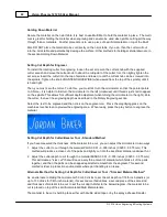
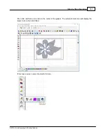
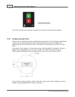
Some graphics have portions that do not need to be engraved and are within the boundaries of outside

vector outlines. Using the Flower example file, import the file to vectorize the bitmap, then select the

Break Path icon to separate the individual outlines.

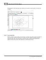
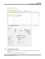
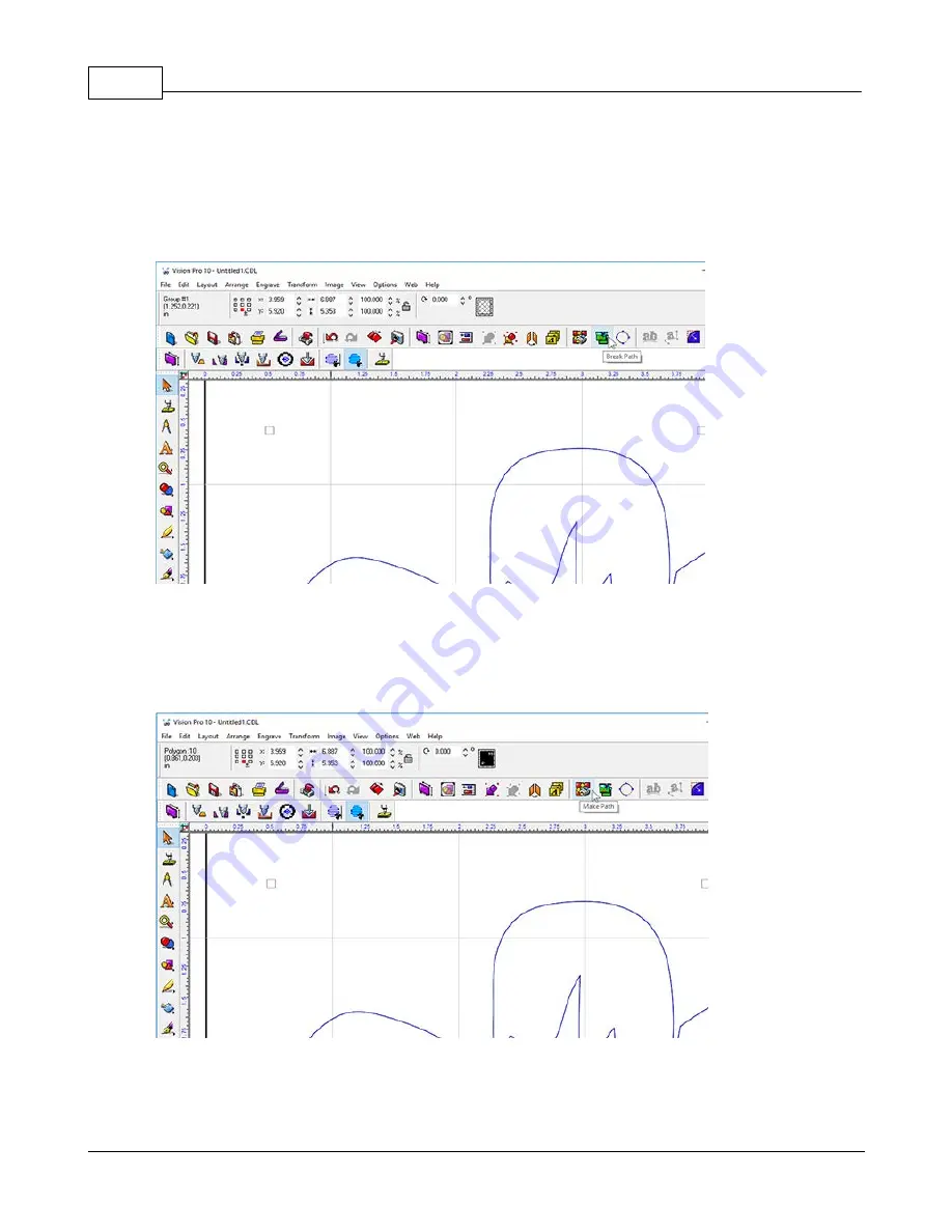
Next, we will need to create a path. The Vision Express software has an intelligent path tool that will

automatically detect portions of the graphic that are within outside vector lines and will create a hatch fill

with the center portions left as unfilled. Press the F3 button on the computer keyboard to select all

items, then select the Make Path icon.

Содержание Phoenix 1212 S5

Страница 1: ... 2018 Vision Engraving Routing Systems Vision Phoenix 1212 S5 User Manual Revised 12 7 2018 ...

Страница 2: ...make no claim to these trademarks While every precaution has been taken in the preparation of this document the publisher and the author assume no responsibility for errors or omissions or for damages resulting from the use of information contained in this document or from the use of programs and source code that may accompany it In no event shall the publisher and the author be liable for any los...

Страница 3: ...eration 53 53 1 Holding Down Material 55 2 Zeroing the Cutter 55 3 Proximity Sensor 57 4 Step by Step Operation 57 Diamond Drag Engraving 58 Example Job 1 Diamond Drag 70 Rotary Engraving 71 Example Job 2 Rotary Engraving 76 Burnishing 78 Example Job 3 Burnishing 88 Profile Cutting 89 Example Job 4 Profile Cutting 94 Vectorizing Bitmaps and Creating Vector Fills 94 Vectorizing a Bitmap in Vision E...

Страница 4: ...7 4 Side Cover Removal 128 5 Motion System Cleaning Lubrication 130 6 Changing the Motor Brushes 131 7 Cleaning the Filter Part VII Troubleshooting 132 132 1 Engraving Problems 136 2 Mechanical Problems Part VIII Optional Accessories 138 138 1 Vacuum Chip Removal System 139 2 Quick Lock Vise 140 3 Hold Down Clamps 142 4 Fixtures 145 5 Clamping Vises ...

Страница 5: ...For information on the Vision Engraving Software see the Vision Engraving Software manual For more information on your individual computer system see your computer s user manual or contact your computer distributor To begin locate the White Blue Dongle or Silver Dongle or Blue Silver USB Stick included with your machine in the Accessories Box Important Note The Vision software is available in two ...

Страница 6: ...is discovered during the warranty period within thirty days of discovery but no later than the last day of the warranty period as described above the user shall contact Vision for instructions regarding disposition of the problem Vision shall at its option either 1 repair the affected product with new or refurbished parts or 2 provide a replacement Any incidental costs including the cost of shipme...

Страница 7: ...claimed No oral or written information or advice given by Vision its Dealers Distributors Agents or Employees shall create a warranty or in any way increase the scope of this warranty Neither Vision nor anyone else who has been involved in the creation production or delivery of the System shall be liable for any direct indirect consequential or incidental damages including damages for loss of busi...

Страница 8: ... a hazardous environment Do not store or use this machine outdoors Do not run this machine in an extremely hot environment Ø Place the equipment in a location with low humidity and a minimum of dust Avoid placing in direct sunlight or in locations with excessive heat Ø Do not expose the equipment to rain or use near water You can clean the equipment with a damp cloth but be sure to unplug it first...

Страница 9: ...airborne Ø Avoid loose clothing neckties gloves rings bracelets jewelry and other items that may get caught in moving parts Ø If your machine does not operate properly in particular if there are any unusual sounds or smells coming from it immediately unplug it and contact Vision s service department or your local distributor Ø Unplug the machine when it is going to be left unused for an extended p...

Страница 10: ...ents to do work it was not intended to do may cause permanent damage to the machine and serious injury may occur to the operator If there are any questions about the abilities of your machine please call the Vision technical support team at 602 439 0600 Ø Do not force the machine to work at excessive speeds The machine will work safely under normal speeds which are material and application depende...

Страница 11: ...stallation Guide ü 1 White Blue or Orange USB security dongle Contains User Manual and Vision Software ü 1 Ethernet Network Cable P N 20 1074 00 ü 1 Power Cord ü 1 0 015 FLX Plastic Cutter ü 1 Non Rotating Diamond 120 Degree ü 1 Quick Lock Vise Large P N 200100 00 ü 1 Spare Motor Belt P N 200507 14 75 ü 1 Allen Wrench Set ü 1 Cutter Wrench P N 200538 00 ü 1 Technical Support Label ü 1 Accessory Sh...

Страница 12: ...e and the work surface Z Axis Stroke 1 standard 1 75 w riser kit Definition the travel distance of the Z axis mechanism or spindle Table Resolution 0002 inch Definition the smallest controlled motion the table is capable of Maximum Speed 2 inches per second 50 8 mm s Spindle Type 11 64 6mm or 1 4 Top Loading Maximum Work Area 12 x 12 Maximum Work Piece Size 17 5 L x Any Width x 3 H Overall Dimensi...

Страница 13: ...Gantry The gantry or bridge is a large rectangular bar suspended across the width of the table in the X axis The carriage assembly is supported and rides on the gantry in the X axis 4 Carriage Cover The cover protecting the Carriage Assembly 5 Y Axis Stepper Motors These motors drive the Gantry and Carriage in the Y Axis direction 6 X Axis Stepper Motor This motor drives the Carriage in the X Axis...

Страница 14: ...o the right countrerclockwise when viewed from the top of the spindle increases the engraving depth by 0 001 inches 12 Spindle Block Houses the spindle assembly 13 Spindle The spindle moves up and down along a linear bearing and attaches to the face of the carriage assembly It rotates the cutting tool when rotary engraving or holds a non rotating cutting tool for diamond drag engraving 14 Drive Be...

Страница 15: ...he sides of the engraver these stainless steel rails with sealed bearings secure the position of the Gantry in the Y Axis direction 20 X Axis Linear Rails Mounted in the middle of the Gantry these stainless steel rails with sealed bearings secure the position of the Carriage in the X Axis direction 21 Edge Guides These guides allow the user to position material on the T Slot Table accurately They ...

Страница 16: ...Vision Phoenix 1212 S5 User Manual 16 2018 Vision Engraving Routing Systems ...

Страница 17: ...hine Mount the vise using the threaded holes in the table baseplate To adjust the height of the T Slot Table the standard 2 3 4 inch Stantions Risers can be removed and replaced with optional 2 inch risers Remove the T Slot Table and remove each riser There are machined flat surfaces on the top of each riser to allow removal installation with an open end wrench NOTE Be sure to label each riser wit...

Страница 18: ...ments CPU Dual Core 2 0GHz or higher Hard Drive 750 GB free space RAM 1GB OS Requirements Operating System Windows 10 32 64 bit Windows 8 32 64 bit Windows 7 SP 1 32 64 bit Requires Service Pack 1 Ports USB port for security dongle Local or network Ethernet port to connect machine Suggested System Requirements CPU Core i3 or faster Hard Drive 1 TB or more RAM 4GB OS Requirements Operating System W...

Страница 19: ...tallation Insert the Vision USB dongle into the USB port on the computer Navigate to the Devices and Drives area on your PC Double click on the Vision icon to open the files on the USB dongle Select the Start or Start exe file to begin Click on the Install Vision Software button ...

Страница 20: ...Phoenix 1212 S5 User Manual 20 2018 Vision Engraving Routing Systems The Vision S5 Software Wizard will guide you through the process of installing the software Press Next to continue Press Install to continue ...

Страница 21: ...Installation 21 2018 Vision Engraving Routing Systems Setup wizard will install the program Select Finish to continue the software installation Choose your preferred language and click ok ...

Страница 22: ...Vision Phoenix 1212 S5 User Manual 22 2018 Vision Engraving Routing Systems The Vision 10 Setup Screen will appear Press Next After accepting the license agreement click on the Next button ...

Страница 23: ...Installation 23 2018 Vision Engraving Routing Systems Select Next or change the destination folder not recommended Select Next to create the folder ...

Страница 24: ...Vision Phoenix 1212 S5 User Manual 24 2018 Vision Engraving Routing Systems The installation will continue ...

Страница 25: ... the left of Phoenix 1212 in the Manufacturer list then select Next If you purchase another engraving system from Vision it can be added to the machine list at a later date from within the Vision software Select the Phoenix 1212 S5 Note The Phoenix 1212 Vice Center Origin S5 is used when using the center vice accessory ...

Страница 26: ...Vision Phoenix 1212 S5 User Manual 26 2018 Vision Engraving Routing Systems Select Continue to install True Type fonts and Vision Engraving Fonts on your computer ...

Страница 27: ...Installation 27 2018 Vision Engraving Routing Systems Click yes to install all additional fonts from your C Drive All system fonts will be installed ...

Страница 28: ...Vision Phoenix 1212 S5 User Manual 28 2018 Vision Engraving Routing Systems Press OK Press on the Finish button ...

Страница 29: ...Installation 29 2018 Vision Engraving Routing Systems Press the Exit button The Vision manuals icon should now appear on your computer s desktop along with an icon for your version of Vision 10 software ...

Страница 30: ...ower cable into the port on the back of the machine Plug in the network cable or the crossover cable to the back of the machine and either plug the network cable into your network your hub or using the crossover cable plug into the network port on the back of your computer NOTE The Ethernet crossover cable is gray and should not be needed If the emergency stop screen appears on the LCD when the ma...

Страница 31: ...n setup will vary depending on how it is connected to the PC The two options for connecting the Phoenix 1212 to the computer are Direct connection to the computer or direct connection using a network hub or switch Both of these methods require the same setup Connection through a company network ...

Страница 32: ...ction to the computer or direct connection using a network hub or switch Once the machine is connected directly to the computer s network port or is connected directly to a network hub or switch with the black Ethernet cable power the machine on The power switch for the Phoenix 1212 is located on the power supply box for the machine Once the machine has initialized the home screen will appear on t...

Страница 33: ... 2018 Vision Engraving Routing Systems Select the Connectivity Screen icon Confirm that the LCD shows the Mode is set to static If the Mode displays DHCP press the mode icon This will change the Mode to display Static ...

Страница 34: ... the Address is set to 192 168 5 101 If the Address is not set to 192 168 5 101 it will need to be changed Press the tools icon Enter the numbers 192 168 5 101 with the numbers on the LCD If you make a mistake you can press the left arrow to erase a number Press the green check mark to accept the value ...

Страница 35: ...LCD should now look like below Press the X to exit the connection screen Press the X to return to the home screen NOTE This follow section is shown on a Windows 10 PC For Windows 7 or Windows 8 the screens are slightly different The IP address of the computer IP address will need to be set to match the machines network settings To set the computer s IP address right click on the network icon in th...

Страница 36: ...ternet settings In Windows 7 and Windows 8 select Open Network and Sharing Center Select Change adaptor options In Windows 7 and Windows 8 select Change adapter settings Right click on the Ethernet adapter shown and select Properties Select Internet Protocol Version 4 TCP IPv5 and select Properties ...

Страница 37: ...ion Engraving Routing Systems Select Use the following IP address and enter 192 168 5 100 for the IP address and enter 255 255 255 0 for the Subnet mask Select OK The Windows network settings are the machine are now configured ...

Страница 38: ...onnection Connecting through an office network Once the machine is connected to the company network port power the machine on The power switch for the Phoenix 1212 is located on the power supply box for the machine Once the machine has initialized the home screen will appear on the LCD screen ...

Страница 39: ...Installation 39 2018 Vision Engraving Routing Systems Select the Settings Screen icon Select the Connectivity Screen icon ...

Страница 40: ...de displays Static press the mode icon This will change the Mode to display DHCP Make a note of the address that is displayed This will be needed at a later step in the setup NOTE If an IP address is not displayed check with your network administrator to confirm that your network is configured for DHCP Press the green check mark button ...

Страница 41: ...ss the X to exit the connection screen Press the X to return to the home screen Open the Vision 10 Software by selecting the Vision Expert 10 Vision Express 10 or Vision Pro 10 icon from the Windows desktop Go to the Engrave menu and select engraving defaults ...

Страница 42: ...Vision Phoenix 1212 S5 User Manual 42 2018 Vision Engraving Routing Systems In the Engraving defaults window select the setup button Select the port tab ...

Страница 43: ...step You can see this address from the machine home screen by pressing settings icon and then the connectivity screen icon Verify that the method is set to Use Production Spooler the Port location is set to TCIP raw and the port is set to 22000 IMPORTANT If more than one driver is installed you must change the IP address in the port tab for all drivers ...

Страница 44: ...Vision Phoenix 1212 S5 User Manual 44 2018 Vision Engraving Routing Systems ...

Страница 45: ...Installation 45 2018 Vision Engraving Routing Systems Next press Apply and OK to save the settings The machine and Vision software are now configured ...

Страница 46: ...home set the first press of the Home Machine button sends the spindle to the current offset and the second press sends the spindle to the machine home checks the limit switches and sets the current offset to home or offset number 1 Job Folder Screen The Job Folder Screen contains five buttons The up arrow moves the cursor up one position The down arrow moves the cursor down one position The green ...

Страница 47: ... top right of the screen The Jog Offset screen has thirteen buttons that control various functions The Offset Number button scrolls through all of the offset numbers Pressing this button increases the offset number by one and goes from 1 to 9 The Preview button shows the outline of the current job and does nothing if there are no jobs in the machine The X X Y Y jog the X and Y axes in that directi...

Страница 48: ...ed later in this section After selecting the desired offset number press the X and Y jog buttons to move the spindle to the desired location With the spindle at the desired offset location press the blue plus Set button to save this location under the offset number displayed on the screen Pressing the green check button will always move the spindle to the offset location corresponding to the offse...

Страница 49: ...or network Addr shows the current IP address of the machine Mask shows the current Sub net Address of the machine Change allows you to type in an IP and a sub net address when in the static mode The mode button allows you to toggle between Static and DHCP To set a static IP address press the mode button until static is displayed Addr will be red then type in the full IP address including and then ...

Страница 50: ...e Remote Vacuum Port On or Off and will be Red when off and blank when on Aux 2 and Aux 3 buttons are not used on the Express S5 machine The Fan button turns the cooling fan On or Off and will be Red when off and blank when on The Spin button turns the Spindle On or Off and works in conjunction with the slider next to it which sets the Spindle RPM s This screen is used to test or troubleshoot thes...

Страница 51: ... to that exact location Measure Feature Press plate size then measure in Vision software The machine goes into measure mode the laser pointer turns on and the machine screen will change to the Measure screen shown below Using the X and Y jog buttons on this screen jog the laser pointer to the top left corner of the desired engraving area and press the green check select mark Using the same X and Y...

Страница 52: ...the machine the Emergency Stop Screen will appear on the Front Panel and not allow the operator to do anything on the machine until the Emergency stop is deactivated Check to make sure whatever caused the Emergency Stop button to be activated has been cleared or repaired and then twist the button until it pops up to clear the Emergency Stop ...

Страница 53: ...n uncut For a detailed explanation on the use of the micrometer for setting cutting depth see Example Job 4 in the Profile Cutting section Using Sacrificial Material Many times double sided tape can be a quick and very secure way to hold material down the the t slot table The downside to using tape is that it will remain on the table and can be a problem to remove A better solution is to place Mul...

Страница 54: ...guides to their top position then lightly tighten the thumbscrews Slide the material you would like to engrave up against the top and left sides of the t slot table the edge guides will stop the material Loosen the edge guide thumbscrews and lower the edge guides until they are even with the material surface or just below the material surface Tighten the edge guide thumbscrews This process should ...

Страница 55: ...a spline wrench commonly referred to as the cutter wrench CAUTION When you loosen the setscrew in this step the cutter may easily fall out of the spindle and can cause cutter tip damage Use one hand to hold the cutter before loosening 3 Gently place a piece of metal against the bottom of the nosecone so as to push the cutter even with the bottom of the nosecone Now the cutter should be flush with ...

Страница 56: ...roximity sensor When setting a depth in the Vision software the proximity sensor should be turned off in the Cut Toolbox in the Vision software program before sending the job to the machine Also make sure that there is no float on the spindle by locking the pressure spring adjuster all the way down Locking the spindle is especially important when engraving into hard surfaces or materials like bras...

Страница 57: ... user read through and practice the techniques in these example files in the sequence they are provided in this manual 5 4 1 Diamond Drag Engraving Engraving Non Rotating In this section we will set up to engrave with a non rotating cutter such as a diamond drag cutter The figure below shows the Vision Phoenix 1212 spindle with a diamond drag cutter The Vision Phoenix 1212 spindle with diamond dra...

Страница 58: ...cribed in the previous section There is no need to adjust the Z Axis height of the machine also known as Set Surface In this type of engraving the Proximity Sensor will automatically sense when the cutter tip contacts the material and will adjust the Z Axis height and cutting pressure Also the spindle does not need to rotate The material selection shown in the next section will preset the engraver...

Страница 59: ...tep Operation 59 2018 Vision Engraving Routing Systems Click on the Plate Size icon The Plate Size window will appear with either the last plate size used or the default size for the Vision Phoenix 1212 engraver ...

Страница 60: ...Vision Phoenix 1212 S5 User Manual 60 2018 Vision Engraving Routing Systems Click on the Current Selection drop down list and select Custom ...

Страница 61: ...Step by Step Operation 61 2018 Vision Engraving Routing Systems Enter the plate size to be engraved for this example 3 x 2 ...

Страница 62: ...Vision Phoenix 1212 S5 User Manual 62 2018 Vision Engraving Routing Systems To add text click on the Text Tools icon The flyout icons will appear then select the Text Compose icon ...

Страница 63: ...n typing text Note that on the top toolbar the various font editing fields have appeared The user should become familiar with the various ways fonts can be formatted with the toolbar options For this example the only change was for the font height which was set to 0 500 Begin typing text to be engraved ...

Страница 64: ...rrange and Distribute Align to Sign Blank Center as shown below from the top toolbar Note that there are several ways to align objects within the Vision software The Break Text warning may appear If so select No If Yes is chosen and more than one line of text has been entered each line will align on top of one another in the center of the plate ...

Страница 65: ...Step by Step Operation 65 2018 Vision Engraving Routing Systems At this point the screen should appear as below ...

Страница 66: ...aced on the engraving table with the upper left corner of the material positioned in the home position upper left corner of the engraving table Note that the Multi Mat material has been placed on the t slot table in order to hold the engraving material in place Select the Engrave icon from the left toolbar ...

Страница 67: ...ut Toolbox will appear and the options for engraving will appear on the top toolbar Make sure the Device selected is for your machine then select the material drop down Select Metals Diamond Drag Press the Engrave button in the cut toolbox to send the job to the machine ...

Страница 68: ...ond its limits When ready to engrave press the green play button on the touchscreen NOTE keep hands and other loose objects away from the engraver during operation Press the Start Button on the engraver to begin the Dry Run The Dry Run feature will automatically activate the red dot laser pointer and show the user where the machine will engrave NOTE If the spindle turns or begins to drop toward th...

Страница 69: ...Step by Step Operation 69 2018 Vision Engraving Routing Systems The finished piece should appear as shown below ...

Страница 70: ...wed into the spindle The cutter knob is REVERSE threaded so in order to tighten the cutter knob turn the knob COUNTERCLOCKWISE when viewed from the top of the spindle until it is hand tight Then you must zero the cutter To do this you must first turn the micrometer so that the pointer points to 0 Note it is helpful to first turn the micrometer to the left clockwise until threads just start to appe...

Страница 71: ...r more or less depth depending on the whether the engraving is acceptable Note be careful not to set the depth of cut greater than the material thickness This will cut completely through the material and potentially cut into the t slot table For a detailed example of running an rotary engraving job please see the following section 5 4 2 1 Example Job 2 Rotary Engraving In this example a sign will ...

Страница 72: ... enter the text using the Frame Text Compose tool as shown below With this tool selected text will automatically be centered and have automatic Kerning In the below example the font was changed to Casual1 with a height of 1 250 inches and a slant of 19 degrees The top and center lines are left justified and the bottom is center justified in order to produce a sloping look ...

Страница 73: ... has been set up select the Engrave Icon from the left toolbar click on the Tool Setup icon and from the Materials selection drop down list select Engravers Plastic Engraving then click on OK In the picture below the Cut Toolbox shows that the Vacuum Prox Dry Run and Spindle are all enabled Since this is the second example job sending a Dry Run job to the engraver is suggested ...

Страница 74: ...e to hold the engraving material in place and press the start button on the machine to begin engraving NOTE The design of the Vacuum Chip Removal System is to clear the debris away from the engraved material and prevent the chips from scratching the surface of the material during operation and or getting trapped between the nose cone and the material when using the proximity sensor function and ca...

Страница 75: ...ion Engraving Routing Systems the engraver to not engrave to the proper depth When the file is complete remove the material from the table HINT Use a light bristle brush to clean out any debris that may remain in the engraved characters ...

Страница 76: ...deep into metals rather it cuts the painted surface off of metals To effectively burnish it is recommended to use an optional EZ Rider burnishing adapter This helps to control the pressure of the cutter applied to the material Burnishing requires less pressure than other types of engraving and the EZ Rider attachment applies the proper amount of pressure for burnishing Installing the EZ Rider is s...

Страница 77: ... Jog Icon Use the arrows to move the spindle over the material that was placed on the T Slot table Lower the burnishing tool with the Z down button until the tip of the burnishing tool touches the material Move the Z down approximately 0 03 0 05 inches 0 5 1 0mm to preload the EZ Rider spring Select the set surface button The Spindle will rise to confirm the surface has been set Select the go to h...

Страница 78: ...ple items with different text engraved on a single 8 x 6 inch 203 x 152 mm piece of coated brass also known as black brass or trophy brass The plate will use a text import function from an external text file that will be copied into a plate template and the Vision software will automatically format the imported text Begin by selecting the Plate Size Icon and setting the engraving area to the stand...

Страница 79: ...rom the top toolbar menu Adjust the number of plates to 1 leave spacing at 0 000 inches width and height to 2 500 and 1 25 inches set the page margins to 0 250 inches as shown then click on Apply Note that the page margins on the toolbar are located such that the top field is for the top margin the left field is the left margin etc ...

Страница 80: ...Vision Phoenix 1212 S5 User Manual 80 2018 Vision Engraving Routing Systems The screen should then appear as below Select the Text Compose Icon ...

Страница 81: ...in the middle of the Plate Object Enter any text in the format you wish to use In this example two lines of text are entered as variables it does not matter what you type The text entered is only for formatting and will be replaced with the text imported from the txt file ...

Страница 82: ...fy the font style Please note that in this example the Width Compression for the text was adjusted In order to adjust the Width Compression select the Menu button edit the Compression field shown below Select all text and select the Width Compression Mode by clicking on the drop down list as shown Change the settings to Always compress or expand text to fit width Method Width compress expand and A...

Страница 83: ... text file was created in order to copy and paste the variables into the Vision software Highlight the text and select copy from the edit menu or right click and select copy Note that in this example the two variables are entered as subsequent lines in the text file and that there may be difficulties when importing from other file formats A simple text file created in Windows Notepad is suggested ...

Страница 84: ...Vision Phoenix 1212 S5 User Manual 84 2018 Vision Engraving Routing Systems To insert the copied text select Layout Plate Object Paste Clipboard Into Plate Click in the center of the plate ...

Страница 85: ...r of text variables selected Also if there are more variables than can be fit into one plate in the Vision software multiple plates or pages are automatically generated for individual output to the engraver The lower right corner of the Vision software screen allows the user to view the individual pages During the Engrave operation the user will select the page to be sent to the engraver ...

Страница 86: ... burnishing application as described in the previous section and select the Engrave icon from the left toolbar then click on the Tool Setup icon chose Metals Burnishing as the material and click on OK If you choose to run a Dry Run as shown to make sure the setup is correct proceed as in prior sections to send the file to the engraver ...

Страница 87: ...p by Step Operation 87 2018 Vision Engraving Routing Systems Note In this example a toolpath was added to the plate objects to show where the name badges will be cut plate objects are shown in image below ...

Страница 88: ...this section we will set up to engrave with a standard engraving cutter and cut completely through engraver s plastic with a cutter beveler The cutter beveler is used to create a contrast on the edge of the cut material The figure below shows the Vision Phoenix 1212 spindle with a rotary cutter beveler ...

Страница 89: ...ravers plastic is used Two different tools will be used one to engrave and one to profile cut the edges As with Example Job 2 the Vacuum Chip Removal System is highly recommended for this application and is shown in this example Prepare Artwork in Vision Software First we draw a rectangle using the shape tools Size the rectangle to be 3 X 1 Set the X bounds to 25 and the Y to 25 to position the ba...

Страница 90: ...ual 90 2018 Vision Engraving Routing Systems Now we round the corners by selecting the rectangle and pressing the round corners icon In the text box put in 100 and click apply Use the Frame Text Compose Tool to add text to the badge ...

Страница 91: ... Systems Now make a male tool path by clicking on name badge and then pressing on the male toolpath icon In the Tool Path screen select the profile cutter you are using the depth and the color you would like to use for your cut path Here we use Red Press Ok ...

Страница 92: ...ometer to the right Zero the cutter then set the engraving depth as described in the Rotary Engraving section Select the text to be engraved and then click on the engrave icon Press the magnifying glass on the machines touchscreen to preview the engraving area When ready press the play button to engrave the material Setting Cut Depth for Cutter Beveler Tool Standard Method If you have measured the...

Страница 93: ... This in effect sets the cut depth to match the material thickness The cutter knob set screw is tightened then the micrometer is adjusted either for a through cut turning clockwise or a kiss cut turning counter clockwise 1 3 clicks Go to the software and click on the red toolpath Press the engrave icon and change the material settings to Engravers plastic Cutter Bevler Now press the engrave icon t...

Страница 94: ...sion Express Software The Vision 10 software has a new and vastly simplified method of creating a vector outline from a bitmap image Vector outlines are automatically created when the bitmap is imported in the drawing The following procedure can be used to import custom logos or images into the Vision 10 software for engraving purposes Compatible file types Whether the user wishes to scan an image...

Страница 95: ...bmp then choose the file and select Import The next screen has only one adjustment Alignment Bitmap Density There is a slider bar for darkening or lightening the image to show more or less detail The default slider position is recommended Select OK and the bitmap will be automatically converted to a vector outline for engraving ...

Страница 96: ...Hatch Fills When an outline of an object needs to have the interior or sections of the interior engraved the Hatch Fill tool is used As an example if a simple circle is drawn in the Vision software but the user wants to engrave the entire circle not just the outline a hatch fill is used to create the vector fill path for the engraver to follow In this section three applications of a hatch fill wil...

Страница 97: ... the recommended overlap for the Hatch Fill would be 0 020 x 25 0 005 inches To produce an overlap of 0 005 inches subtract 0 005 from the cutter tip width 0 020 0 005 0 015 Tool width If a cutter tip of 0 050 is used then the overlap would be 0 050 x 25 0 0125 inches so the Tool width for the Hatch Fill would be 0 050 0 0125 0 038 inches The user can experiment with different Fill angles and Fill...

Страница 98: ...ing Routing Systems Filling Outline Text Hatch fills can be applied to outline text but not single line text In the below example Arial text was used by selecting the Frame Text Compose icon and clicking in the middle of the plate to create the text as shown ...

Страница 99: ...ext with the Select Tools icon Click on the Select Tools icon and select the text to apply the hatch fill to Select the Hatch Fill icon As with the previous example the hatch fill is applied Adjust the Tool width Tool angle Tool style and color as desired then select Close The file is ready to be sent to the engraver ...

Страница 100: ... the file to vectorize the bitmap then select the Break Path icon to separate the individual outlines Next we will need to create a path The Vision Express software has an intelligent path tool that will automatically detect portions of the graphic that are within outside vector lines and will create a hatch fill with the center portions left as unfilled Press the F3 button on the computer keyboar...

Страница 101: ... 101 2018 Vision Engraving Routing Systems Then click and hold on the node in the center of the graphic The automatic detection will display the areas that can be hatch filled If this looks correct select the Hatch Fill icon ...

Страница 102: ...ix 1212 S5 User Manual 102 2018 Vision Engraving Routing Systems The hatch fill will be applied Adjust the tool options as desired and select Close from the toolbar menu The file is ready to be sent to the engraver ...

Страница 103: ...nd using the Jogger and Red Dot Laser Pointer together Both of these techniques will assist the user when engraving more challenging applications 5 5 1 Setting and Using Custom Home Positions To set the home position of the machine to the upper left hand corner of the engraving area place the material in this example the cell phone case on the engraving table and secure it Press on the jog Icon fr...

Страница 104: ...ngraving Routing Systems The software defaults to offset 1 top left corner of engraving table so we will need to tell it to use this custom home in the software Go to the Vision 10 software click on the tool path to be engraved and press the engrave icon ...

Страница 105: ...uting Systems Now press the Tool Setup button 5 5 2 Using the Measure Feature The Measure Feature allows the user to jog to the material and set plate size using the laser feature of the machine Open up the vision software and press the plate size icon ...

Страница 106: ...e measure button Use the touch panel on the machine to Jog to the top left of the area to be engraved Press the yellow select button in the middle of the screen and the yellow background will disappear Now jog to the bottom right of the area to be engraved and press the green select button ...

Страница 107: ...p by Step Operation 107 2018 Vision Engraving Routing Systems The touchscreen will now show a magnifying glass in the center Press this to preview the new plate size engraving area using the machines laser ...

Страница 108: ...will walk the user through the process In this example a 3 inch diameter piece of acrylic will be used and a circular engraving area will be designed If you are using a rectangular item the process will be very similar and differences are noted here detailing the variations in the job set up First place the material somewhere on the table If using a square item make sure it is square to the table ...

Страница 109: ...gger button on the machines touch screen Now press the magnifying glass to turn on the laser Use the arrows to jog to the top edge of the piece of acrylic Write down the Y position readout For rectangular items move the laser pointer to the top left corner of your engraving area ...

Страница 110: ...w draw guidelines using the measurements we wrote down To add a guideline click with the right mouse button anywhere within the plate area Now select Edit Guides Select the horizontal guide icon in the top left corner and enter your Y measurement in the Y entry field Click add and then enter your second Y location Press add again and then click on the vertical icon in the top left corner of the wi...

Страница 111: ...s icon from the left toolbar and then select the circle tool or rectangle tool for a rectangle In Order to make sure we will be located properly we will use the machines dry run feature Send the file to the engraver Instead of pressing play on the touch screen press the magnifying glass ...

Страница 112: ...ea The Vision 10 software will automatically position the job based on this center location An illustration of this process is shown below For simplicity in this example a circular piece of acrylic will be engraved The material is 3 inches in diameter and an engraving area of 1 75 x 0 75 needs to be centered on the piece of acrylic Referencing the drawing below the job will be quickly set up using...

Страница 113: ...Step by Step Operation 113 2018 Vision Engraving Routing Systems ...

Страница 114: ... Vision Engraving Routing Systems The Plot widow will appear and from the Selected Driver drop down list select the Phoenix 1212 S5 Vise driver If this driver has not been installed refer to the section Installing Additional Drivers Select Setup ...

Страница 115: ...2018 Vision Engraving Routing Systems Under the Installed Drivers section make sure the Phoenix 1212 S5 Vise driver is selected then select Create custom copy of selected driver Type in Phoenix 1212 Center Driver then click on OK ...

Страница 116: ...graving Routing Systems Click on Apply then click on OK Select the Phoenix 1212 Center Driver we just created from the Selected Driver drop down list Change the settings in the Move fields to 0 for both X and Y move click on Apply and then click on Close ...

Страница 117: ...ision Engraving Routing Systems Set the plate size to match the engraving area you determined for your item In this example a 1 75 x 0 75 size was entered Make sure the Selected Driver is the Phoenix 1212 Center Driver then click on OK ...

Страница 118: ...e need to set the home position set offset for the item we are engraving Move the spindle to the center of the engraving area In this case it is the center of the 3 0 piece of acrylic Press the Set Offset button on the engraver This is now the center of the engraving area for our job The below picture shows the spindle positioned over the center of the engraving area ...

Страница 119: ...e top toolbar Select Engrave from the Cut Toolbox then press the Start button on the engraver to begin engraving the job You may want to perform a dry run before engraving to check for setup errors Since we have now created a Center Driver if we want to use the centering feature in the future we only need to select the Center Driver from the Device drop down list and set the home position set offs...

Страница 120: ...ion of this knob To change the engraving pressure the knob must be rotated which changes the preload on the spring and therefore the amount of pressure applied by the cutter tip on to your material This is normally performed for diamond drag engraving only More pressure will produce a deeper engraving To increase the engraving pressure the knob must be rotated clockwise when viewed from the top of...

Страница 121: ...Step by Step Operation 121 2018 Vision Engraving Routing Systems ...

Страница 122: ...le from the top menu bar then select Install and click on Cutting Devices The Installation Wizard will begin The Driver Installation Wizard window will appear Select the machine series from the Manufacturer list on the left side by placing a check mark in the box of the machine you wish to use the driver for then select the driver s by placing a check mark in the box to the left of the driver s yo...

Страница 123: ...Step by Step Operation 123 2018 Vision Engraving Routing Systems ...

Страница 124: ...loses automatically the driver s will then be available in the Device drop down list If you wish to uninstall driver s simply follow the above procedure and deselect the drivers by removing the check mark to the left of the machines you want to uninstall from the Manufacturer section of the Driver Installation Wizard window then click on Next to remove those drivers ...

Страница 125: ...quired after using Multi Mat For most situations the answer is no However Multi Mat does leave a slight residue on the back of some engraving plates What happens if I engrave through the engraving material into Multi Mat Is it ruined Multi Mat has a self healing feature Small cuts in the surface of Multi Mat should not cause a problem and seem to heal Of course continued cuts over a long period of...

Страница 126: ...ne The nose cone retainer ring the nose cone and the micrometer collar should all be removed and cleaned using a vacuum or compressed air The three nose cone components should be removed and cleaned at least every day or as frequently as necessary Failure to clean the nose cone regularly will result in premature spindle failure Vacuum Maintenance only with the vacuum chip removal option When you n...

Страница 127: ...rom Vision Engraving Systems Having the correct belt size ensures proper operation of your engraver NEVER EXCESSIVELY STRETCH THE BELT Step 1 Remove 4 screws on each side of Carriage Cover 8 screws total Lift cover up to remove Step 2 Roll Belt up toward top of spindle pulley Step 3 Rotate Spindle pulley while rolling belt up Belt will roll over top lip of pulley Reverse these steps to install a n...

Страница 128: ...s can then slide forward and up 6 5 Motion System Cleaning Lubrication Lubricating the X Axis Y Axis and Z Axis Leadscrews and Linear Rails A light lubrication of the X Y and Z Axis leadscrews should be performed after every month of usage Use Teflon Free Silicone lubricant spray only Spray a light coating along the entire leadscrew Note A nozzle extender attached to the aerosol spray can help fac...

Страница 129: ...lied to the rail surfaces Spread the oil over the rails using a cotton swap or your finger Lubrication frequency will depend on usage and the types of materials being engraved The Z Axis linear bearing should be wiped down with a clean dry cloth every week and a few drops of machine oil such as 3 in 1 Oil should be applied to the rail surfaces as per above Carriage and Side Covers Removed for Clar...

Страница 130: ...f the machine and they will typically last for several years NOTE Unplug the machine from its power source before attempting this procedure Failure to unplug the machine could present an electrical shock hazard To easily access the motor brushes for removal it is recommended to remove the top cover and carriage cover as described in the previous section Use a flat blade screwdriver to loosen the m...

Страница 131: ...machine It is recommended that the input fan filter be removed weekly and cleaned to ensure proper cooling of the electronics 1 Unplug the power cable that goes into the back of the machine 2 Remove the filter guard by using a small flat blade screwdriver to pop the guard open 3 Remove the filter and blow out the filter with low pressure compressed air 4 Replace the filter and filter guard by snap...

Страница 132: ...e able to salvage it by re engraving the job or you may be able to analyze the problem and prevent repeating it Perhaps the plate moved during engraving Removing it without inspection would prevent you from detecting this problem Problem When using a nose cone the engraving is shallow across the top or left margin of your plate It engraves properly when the spindle is away from the edge Possible s...

Страница 133: ...raving 2 Use a plastic nose cone instead of a metal one 3 The nose cone may be damaged Inspect for burrs or roughness Try using an emery cloth to polish the nose 4 Use less spindle spring pressure Excessive down pressure will leave a rub mark on almost any plastic material Problem You are not using a nose cone and you have uneven engraving Possible solutions 1 Switch to a nose riding method 2 Use ...

Страница 134: ...rial it should be left to right 3 The cutter may be dull or worn 4 The material is not securely fastened to the table Problem Ragged engraved characters Possible solutions 1 If the quality of cut is ragged or exhibits steps there may be play in the cutter This could be in the gap between the cutter and the spindle shaft Maybe the shaft is worn or the spindle bearings need to be replaced Once a sha...

Страница 135: ...isher The more common carbide tools may have difficulty getting through the surface and are more easily worn thus sometimes skipping across the surface 3 Increase the pre load of the burnishing adapter 4 Try other materials Same reasons as above Some materials are too tough to engrave ...

Страница 136: ...the cause of the unusual noise Perform a dry run with a No changes to the machine b The cutter removed c The engraving motor turned OFF This is done in the Cut Toolbox by turning the Spindle control to OFF If the noise persists it may be confined to the X Y or Z axis Check for proper lubrication of lead screws Follow lubrication instructions in the Maintenance section If the noise persists further...

Страница 137: ... obstructions that may prevent proper rotation 3 The spindle bearings may need to be replaced Problem Spindle motor will not turn on Possible solutions 1 Check motor brushes Problem Motor belt will not stay on pulley Possible solutions 1 Motor belt is probably worn and needs to be replaced ...

Страница 138: ...al which will cause engraving cutting depth inconsistencies as well as potentially scratch the surface of the material The vacuum chip removal system is designed to simplify the engraving process and minimize wear and tear on the engraver It uses a vacuum nose cone to remove chips created during the engraving process before they have the chance to create problems The quiet pump coupled with the mi...

Страница 139: ...n the quick lock vise locking screw Once this is done the material can easily be secured by turning the quick lock vise handle When changing the engraving material simply loosen the quick lock vise handle remove the engraved material put the new material in and tighten up the quick lock handle Note For larger pieces of material you may need to put a small piece of double sided tape on the tslot ta...

Страница 140: ...clamp onto the T slot table surface and position it over the edge of the engraving stock The downward clamping force eliminates bowing This clamp can be used with material up to 1 4 thick Push Down Clamps This double sided clamp secures items from the edge It is ideal for heavy duty items that are being cut contoured or engraved ...

Страница 141: ...in most applications This clamp will hold material thicknesses of 020 032 062 and 125 by rotating the clamp and tightening a thumbscrew Corner Clamps This clamp is designed to hold down square or rectangular plates By lining up the V cut out of the clamp with the corner of the plate the engraver is allowed maximum engraving space It will hold material as thin as 1 32 ...

Страница 142: ...tems 8 4 Fixtures Universal Pin Fixtures Available for the Versa Vise T slot table and Self Centering Vise Also usable with other computerized engravers and Pantographs These fixtures enable engraving on uniquely shaped items such as pens lighters knives keychains and more ...

Страница 143: ...time Engrave multiple notary seals paperweights and a variety of other circular items With a place for the eye of medallions this clamp adapts to any vise or table that has a T slot system Seal Fixture The Seal Fixture enables engraving on notary seals medallions coasters paperweights dog tags and other round objects Usable with the Quick Lock or Versa Vise ...

Страница 144: ...most computerized engravers and Pantographs It is also usable with the Versa Vise and Self Centering Vise Pen Medallion Fixture This is a double sided fixture that when turned in one direction accommodates a pen and when turned in the other direction accommodates a medallion seal or other circular item With a space for the eye of the medallion this fixture is usable with the Versa Vise or Quick Lo...

Страница 145: ...specifically designed for T slot table users The cam type locking device allows for quick changing of parts This vise is supplied with a removable front clamping plate which allows for the holding of thicker items Self Centering Deep Vise This self centering vise allows for easy setup of odd shaped items up to 3 1 4 deep ...

Страница 146: ... Vision Engraving Routing Systems Small Self Centering Vise This fixture allows you to hold various small items such as nameplates signs and placards Dowel pin settings allow this item to work with most Vision fixtures for even more versatility ...

Страница 147: ...Optional Accessories 147 2018 Vision Engraving Routing Systems ...

Страница 148: ......

Отзывы: