74
Viscount Concerto III - Operating Manual
2.6 THE CONNECTIONS ON THE REAR PANEL
38
39
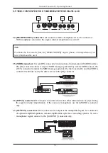
38. [EXT. +12V DC] connector:
this socket can be used to obtain the +12 VDC voltage for remote
switch-on of the amplifiers connected to the [MAIN OUTPUTS] connectors using the [EXT.SPK]
switch on the right-hand side panel (see point 4 of section 2.1).
39. [MAIN OUTPUTS] connectors:
Jack sockets for connecting optional remote speakers.
The signal distribution is as follows:
o
[OUT 1 (GENERAL)]:
if just these jacks are connected, these outputs will carry the church
organ voices of the entire organ, and the Orchestra voices.
o
[OUT 2 (+ORCHESTRA)]:
if these jacks are also connected, these outputs will carry the
Orchestra voices, while the church organ voices will be subdivided on the basis of the
AMPLIFICATION SYSTEM function, which can be set on the display.
o
[ORCHESTRA]:
if these jacks are also connected, these connectors will carry the
Orchestra voices, while the [OUT 1] and [OUT 2] will carry the church organ voices on the
basis of the AMPLIFICATION SYSTEM function.
In the Concerto III version without Orchestra voices, the outputs dedicated to these voices are
absent, so the setup will be:
o
[OUT 1 (GENERAL)]:
if these jacks are connected, these outputs will carry the voices of
the entire organ.
o
[OUT 2]:
if these jacks are also connected, the sections will be shared between the [OUT 1]
and [OUT 2] outputs basis of the AMPLIFICATION SYSTEM function settings.
N.B.
-
The [MAIN OUTPUTS] outputs are unaffected by the general volume control function
implemented using the [GENERAL] slider on the central panel.
-
For further information about the AMPLIFICATION SYSTEM function, refer to point 6.4.


