Chapter 2 Decentral block periphery CAN-Bus CANopen
Manual VIPA System 100V
2-44
HB100E - SM-CAN - Rev. 15/02
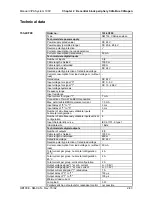
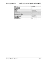
Order no.
153-4CF00
of a load
Parallel switching of outputs for increased power
not possible
Actuation of digital input
9
Switching frequency with resistive load
max. 1000 Hz
Switching frequency with inductive load
max. 0.5 Hz
Switching frequency on lamp load
max. 10 Hz
Internal limitation of inductive shut-off voltage
L+ (-52 V)
Short-circuit protection of output
yes, electronic
Trigger level
1.5 A
Number of operating cycle of relay outputs
-
Switching capacity of contacts
-
Output data size
1 Byte
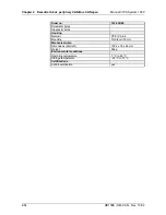
Status information, alarms, diagnostics
Status display
green LED per channel
Interrupts no
Process alarm
no
Diagnostic interrupt
no
Diagnostic functions
no
Diagnostics information read-out
possible
Supply voltage display
yes
Group error display
red SF LED
Channel error display
none
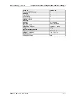
Isolation
Between channels
-
Between channels of groups to
-
Between channels and backplane bus
-
Between channels and power supply
-
Max. potential difference between circuits
-
Max. potential difference between inputs (Ucm)
-
Max. potential difference between Mana and
Mintern (Uiso)
-
Max. potential difference between inputs and Mana
(Ucm)
-
Max. potential difference between inputs and
Mintern (Uiso)
-
Max. potential difference between Mintern and
outputs
-
Insulation tested with
DC 500 V
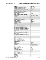
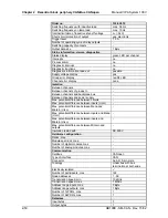
Hardware configuration
Racks, max.
-
Modules per rack, max.
-
Number of digital modules, max.
-
Number of analog modules, max.
-
Communication
Fieldbus CANopen
Type of interface
CAN
Connector
Sub-D, 9-pin, male
Topology
Linear bus with bus
termination at both ends
Electrically isolated
9
Number of participants, max.
126
Node addresses
1 - 99
Transmission speed, min.
10 kbit/s
Transmission speed, max.
1 Mbit/s
Address range inputs, max.
1 Byte
Address range outputs, max.
1 Byte
Number of TxPDOs, max.
1


