Man-1131_Hydrosense_HSCP_01
Page 17 of 18
This enables each zone to be given a text description allowing easier identification of any zones showing an
abnormal condition.
22. Hydrowire commissioning details
22.1 Installation
22.1.1 Lengths of Hydrowire should be laid on the floor in the protected area such that the distance
between any two Hydrowires is no more than 2 metres.
22.1.2 For localised protection of sources of potential water leakage, such as air conditioning
systems or water filled radiators, the distance between Hydrowires may be greater.
22.1.3 The cable should be installed such that it remains in contact with the floor along as much of
its length as possible. This may require the use of P clips, particularly in areas where the
cable may be disturbed.
22.1.4 Although the construction is quite sturdy, the cable may be damaged by crushing or excessive
bending. A bend radius of 150 mm is recommended as a minimum.
22.1.5 The end of the Hydrowire must be terminated with an end of line plug (K2110).
22.1.6 The terminating connection box (K2106) should be secured to the wall or floor such that the
Hydrowire does not have to be stretched or pulled to reach it.
22.1.7 The installed Hydrowire should consist of a K2106 connection box, Hydrowire cable (K2104 or/and
K2105) and end of line plug unit (K2110).
22.1.8 The red warning label should be left such that it is clearly visible.
22.1.9 Hydrowire should not come into contact with surface temperatures greater than 70°C.
22.1.10 Lengths greater than 50 metres are not allowed.
22.2 Connection to Control Panel
22.2.1 The K1622 connection box, when triggered presents an impedance of 470 R to the 24 volt
circuit from the control panel.
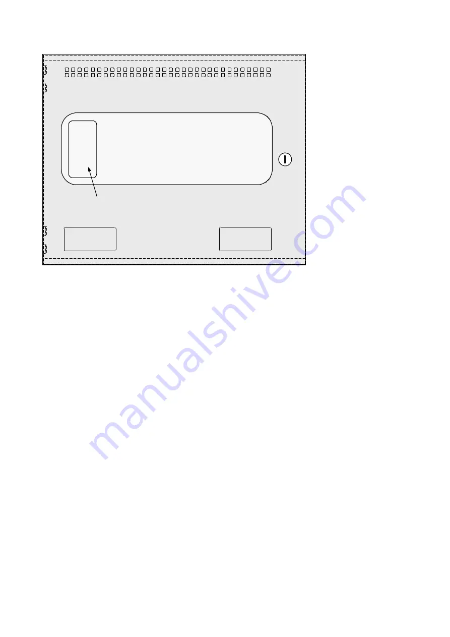
ZONE DESIGNATION LABEL


