66250694-EN - V 3.4 - 31/08/16
17
VRVK/6358 Series Vandal Resistant “6 wire Bus” videokit
VRVK/6358 Series - Installation handbook
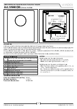
Art. 6358
3.5" hands free colour display digital videophone
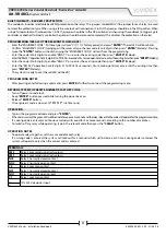
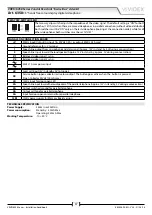
2 WAY DIP-SWITCH (SW2)
The two way dip-switch adjusts the impedance of the video signal. The default setting is “ON” for both
switches (75 Ohm): when there are more videophones in parallel connection (without video distributor)
both switches must be “ON” only on the last videophone (looking at the connection order) while for all
other videophones both switches must be set to “OFF”.
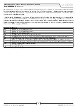
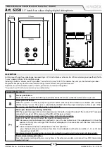
SIGNALS ON CONNECTION BOARD
+V
20Vdc Input/Output (As input 16÷20Vdc 0,5A – as output 20Vdc 0,5A max)
–
Ground reference for +V terminal.
1
Speech line output from microphone and data signal (Approx. 12V in stand-by, 5V during a conversation)
2
Speech line input toward the loudspeaker (Approx. 12V in stand- by, approx. 3V during a conversation)
V1
Balanced video signal 1 sync.–
V2
Balanced video signal 2 sync.+
24Vac 1A max power input
LB
Local call input (5V in standby, 0V to trigger)
SB
Service button (open collector) active low output. The button goes active when the button is pressed
(Open Collector 24Vdc 100mA max)
LD
12Vdc input for door-open LED
2A
Speech line input toward the loudspeaker of the parallel telephone (Approx. 12V in stand-by, 3V during a conversation)
3A
Output switched ground for parallel telephone
4A
Output call tone for parallel telephone
5A
Input for door-open command from parallel telephone
12M
12Vdc power supply for Memory Board version
TECHNICAL SPECIFICATION
Power Supply:
24Vac in or 20Vdc in
Power consumption:
Stand-by: 50mA Max
Operating: 250mA Max
Working Temperature: -10 +50 °C


