66250694-EN - V 3.4 - 31/08/16
9
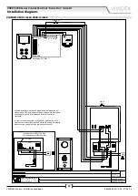
VRVK/6358 Series Vandal Resistant “6 wire Bus” videokit
VRVK/6358 Series - Installation handbook
When the door open relay operating mode is set to “capacitor discharge”*, one terminal of the electric lock must be connected to
ground while the second must be connected to “NO” terminal. The “NO” terminal will supply a temporary voltage when the speaker
unit receives the door open command. In “dry contact” mode the “NO” terminal is internally linked to “C” terminal when the speaker
unit receives the door open command.
* When “capacitor discharge” operating mode is set, one terminal of the electric lock must be connected to the ground while the
second one must be connected to “NO” terminal. The “NO” terminal will supply a temporary voltage when the speaker unit receives
the door open command (we suggest to use a 12Vac/dc 1A max electric lock). Setting “dry contacts” operating mode, when the
speaker unit receives the door open command, the “NO” terminal will be internally linked to the “C” terminal for the programmed
time (switch 4 of the 4 way dip-switch bank).
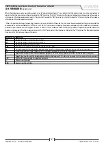
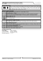
SIGNALS (TERMINALS)
NO
Door open relay normally open contact
NC
Door open relay normally closed contact
C
Door open relay common contact
PTE
Active low input to control directly the door open relay
SL
Active low output to enable the enslavement relay for video signal exchange (active with a call in progress)
BS
Input/Output busy signal (approx 12V in stand-by, approx 0V with a call in progress)
2
Speech line output from the microphone (approx 12V in stand-by, approx 3V with a conversation in progress)
1
Speech line input toward the loudspeaker and data signal (approx 12V in stand-by, approx 5V with a conversation in progress)
+12
12Vdc 0.3A max output to supply accessories
—
Power input ground
+20
Power input 16÷20Vdc
Art. VR4KAMK
Speaker unit

