background image

66250694-EN - V 3.4 - 31/08/16

5

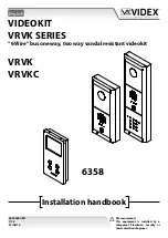
VRVK/6358 Series Vandal Resistant “6 wire Bus” videokit

VRVK/6358 Series - Installation handbook

General directions for installation

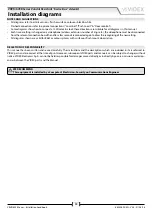
CONNECTION TO MAINS
The system must be installed according to national rules in force, in particular we recommend to:

•  Connect the system to the mains through an all-pole circuit breaker which shall have contact separation of at least 3mm in each 

pole and shall disconnect all poles simultaneously;

•  The all-pole circuit breaker shall be placed for easy access and the switch shall remain readily operable.

POWER SUPPLY INSTALLATION
•  Remove the terminal side covers by unscrewing the retaining screws;

•  Fix the power supply to a DIN bar or directly to the wall using two expansion type screws;

•  Switch off the mains using the circuit breaker mentioned above and then make the connections as shown on the installation diagrams;

•  Check the connections and secure the wires into the terminals;

•  Replace the terminal covers and fix them using the relevant screws;

•  When all connections are made, restore the mains.

CABLE SIZE
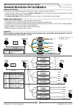
Video connections and Audio connections must be wired in twisted pair: pair the video lines (terminals/signals “V1” and “V2”), 

pair the audio lines (terminals /signals “1” and “2”).

+V *

– *

1

V1

V2

2

Power 

supply

Videophone

Up to 40mt

2 wires

Ø 1mm2

20mt max

Outdoor 

station

BROWN

ORANGE

BLUE

GREEN

WHITE/BROWN

WHITE/ORANGE

WHITE/BLUE

WHITE/GREEN

Distance Suggested cables type
Up to

40mt

CAT5/CAT6 FTP/UTP

AWG24

* Couple the two wires to 

double the section.

1

V1

V2

+V

2

1

V1

V2

+V

2

1

V1

V2

+V

2

Power 

supply

Videophone

Up to 50mt

Outdoor 

station

Outdoor 

station

Outdoor 

station

"+V" and "–"

Ø 0.35mm2

"V1" and "V2"

Ø 0.35mm2 Twisted pair

"1" and "2"

Ø 0.35mm2 Twisted pair

20mt max

2 wires

Ø 1mm2

from 50 to 100mt

"+V" and "–"

Ø 0.75mm2

"1" and "2"

Ø 0.5mm2 Twisted pair

"V1" and "V2"

Ø 0.5mm2 Twisted pair

from 100 to 200mt

"+V" and "–"

Ø 1.5mm2

"V1" and "V2"

Ø 0.75mm2 Twisted pair

"1" and "2"

Ø 0.75mm2 Twisted pair

Distance Suggested cables type
Up to

50mt

Belden 9746 or equivalnet

4 pair (8 cores) 0.35mm2

AWG22 - 48Ω/Km

From

50 to 

100mt

Belden 9690 or equivalnet

3 pair (6 cores) 0.8mm2

AWG18 - 19.2Ω/Km

From

100 to 

200mt

Belden 9157 or equivalnet

4 pair (8 cores) 0.8mm2

AWG18 - 19.2Ω/Km

Содержание VRVKC Series

Страница 1: ...16 VIDEOKIT VRVK SERIES 6 Wire bus one way two way vandal resistant videokit Installation handbook VRVK VRVKC We recommend This equipment is installed by a Competent Electrician Security or Communications Engineer 6358 English ...

Страница 2: ... methods of operating the electric lock 1 Dry contact relay 2 capacitor discharge circuit Facility for the connection of other modules supplied by 12Vdc 300mA max Programmable number of call tone rings from 2 to a maximum of 8 Input for local door bell push button Programmable timed privacy function from 15 minutes to a maximum of 8 hours Door open status LED additional wire required from the door...

Страница 3: ...M Cameraunit 1Art VR4KAMK 1 1buttonspeakerunit 1Art 4852 Flushmountingbox 1 Colour videophone Art 6358 1 Power supply Art 850K VRVK 1S 6358 surface mounting 1 Outdoor station composed of 1Art VR4KCM Cameraunit 1Art VR4KAMK 1 1buttonspeakerunit 1Art 4882 Surfacemountingbox 1 Colour videophone Art 6358 1 Power supply Art 850K TWO WAY VERSIONS VRVK 2 6358 flush mounting 1 Outdoor station composed of ...

Страница 4: ...kmodule 1Art 4853 Flushmountingbox 1 Colour videophone Art 6358 1 Power supply Art 850K VRVKC 1S 6358 surface mounting 1 Outdoor station composed of 1Art VR4KCM Cameraunit 1Art VR4KAMK 1 1buttonspeakerunit 1Art VR4KCL Codelockmodule 1Art 4883 Surfacemountingbox 1 Colour videophone Art 6358 1 Power supply Art 850K TWO WAY VERSIONS VRVKC 2 6358 flush mounting 1 Outdoor station composed of 1Art VR4KC...

Страница 5: ...relevant screws When all connections are made restore the mains CABLE SIZE Video connections and Audio connections must be wired in twisted pair pair the video lines terminals signals V1 and V2 pair the audio lines terminals signals 1 and 2 V 1 V1 V2 2 Power supply Videophone Up to 40mt 2 wires Ø 1mm2 20mt max Outdoor station BROWN ORANGE BLUE GREEN WHITE BROWN WHITE ORANGE WHITE BLUE WHITE GREEN ...

Страница 6: ...ignal During the conversation it is not possible to open the door but the key LED on the door station switches on for the program med time Incorrect position of J2 jumper Electriclockwiresunconnectedorinshort Wrong electric lock type Check J2 position on the door station Check connection Check that the electric lock type ac or dc is suitable for the J2 position chosen Speech only from outside to i...

Страница 7: ...t VR4KAM2W or Videokit combined with Art VR4KAMK The camera can be set for composite video signal coax cable or for balanced video twisted pair cable SIGNALS TERMINALS SL Active low input to enable the camera lightning the jumper JP2 must be moved in SL position SB Heater ground input V2 Balanced video signal sync V1 Balanced video signal sync V Coax video signal Ground input SB Heater plus input ...

Страница 8: ...duration of the door opening time CONTROLS SPEAKER MICROPHONE VOLUME Trimmer to adjust the speaker volume Rotate clockwise to increase or anti clockwise to de crease Trimmer to adjust the microphonez volume Rotate clockwise to increase or anti clockwise to de crease SETTINGS DIP SWITCH JUMPERS 4 WAY DIP SWITCH First two switches are used to set the speaker unit address the speaker unit address is ...

Страница 9: ...n command we suggest to use a 12Vac dc 1A max electric lock Setting dry contacts operating mode when the speaker unit receives the door open command the NO terminal will be internally linked to the C terminal for the programmed time switch 4 of the 4 way dip switch bank SIGNALS TERMINALS NO Door open relay normally open contact NC Door open relay normally closed contact C Door open relay common co...

Страница 10: ...TION In order to achieve the best results from the schematics described it is necessary to install only originalVIDEX equipment strictly keeping to the items indicated on each schematic and follow these General Directions for Installation Thesystemmustbeinstalledaccordingtonationalrulesinforce inanycasetherunningofcablesofanyintercomunitmustbecarried out separately from the mains All multipair cab...

Страница 11: ...existing code then press ENTER Melody Enter the RELAY 2 operation time 2 digits 01 to 99 I E 05 5 seconds 00 remain open time or re enter the existing time then press ENTER Melody The system is ready to use the red LED will be off PROGRAMMING NOTES After pressing enter following a command press ENTER a further twice to exit the programming menu RETURN SYSTEM TO PRESET ENGINEER S FACTORY CODE Turn ...

Страница 12: ...111111 FACTORY PRESET TYPE AGAIN SIX TIMES 1 OR THE NEW ENGINEER S CODE 4 TO 8 DIGITS TWO DIGITS 01 TO 99 I E 05 5 SECONDS 00 REMAIN OPEN CODE TO ENABLE RELAY 1 4 TO 8 DIGITS CODE TO ENABLE RELAY 2 4 TO 8 DIGITS TWO DIGITS 01 TO 99 RED LED WILL BE OFF Press Enter Red LED will be ON Press Enter Melody Press Enter Melody Press Enter Melody Press Enter Melody Press Enter Melody TECHNICAL SPECIFICATIO...

Страница 13: ...ation handbook 4000 Series Surface and flush mounting door station installation H G H Y G C F E D B A C L H L P O N M H M M C Q P C D W N N C H fig 1 fig 8 fig 4 fig 5 fig 6 fig 7 fig 3 fig 10 fig 11 fig 15 fig 12 fig 16 fig 13 fig 17 fig 14 fig 18 fig 2 fig 9 EXAMPLE INSTALLING A FOUR MODULE OUTDOOR STATION ...

Страница 14: ...the system has been tested and is working correctly move back the module support frames carefully fix them to the surface box using the screwdriver provided P torx end and the pin machine torx screws Q Fig 11 Note do not over tighten the screws more than is necessary INSTALLING A FLUSH MOUNTING DOOR STATION When flush mounting and the number of modules is greater than 3 the required back boxes nee...

Страница 15: ...ivates LED switched on or disables LED switched off the privacy service The service is automatically disabled when the programmed privacy time expires When the service is enabled the videophone does not receive calls Door open intercommunicating call button With the speech lines open to the entrance panel press this button to open the door If the terminal LD is properly connected the relevant LED ...

Страница 16: ... If the button is not pressed for 10 seconds the videomonitor will switch off The videomonitor will re vert to duplex speech when another call is made LEDS FIG 1 LED Privacy on LED It illuminates when the privacy service is enabled LED Generic use LED It is controlled from the terminals DOL and DOL Normally used to signal the door status open or closed LED ON LED It illuminates when the videophone...

Страница 17: ...nd data signal Approx 12V in stand by 5V during a conversation 2 Speech line input toward the loudspeaker Approx 12V in stand by approx 3V during a conversation V1 Balanced video signal 1 sync V2 Balanced video signal 2 sync 24Vac 1A max power input LB Local call input 5V in standby 0V to trigger SB Service button open collector active low output The button goes active when the button is pressed O...

Страница 18: ...sert the wall plugs B and fix the base with the screws C feeding the wires D through the hole E If you have used the box 503 fix the base to the wall through the holes F using the screws C 4 As shown in Fig 4 connect the wires to the removable terminals following the provided installation diagram Connect the terminal blocks to the electronics contained in the cover as shown in Fig 5 Test system be...

Страница 19: ...the relevant connection board then after a few seconds reconnected again to allow the recognizing of the new setting All diagrams shown are valid for B W or colour systems with surface or flush mount door station DECLETION OF RESPONSIBILITY This manual has been written and revised carefully The instructions and the descriptions which are included in it are referred to VIDEX parts and are correct a...

Страница 20: ...le Notes Titolo Note Cod File Foglio 1 1 Marco Rongoni vrvk63h 001 dwg 02 12 2015 02 12 2015 Push to Exit Affinche qualsiasi modifica alle impostazioni dei dip switch del videocitofono o del posto esterno venga riconosciuta dal sistema è necessario togliere l alimentazione di rete all impianto e restituirla In order to make the system recognize any modification of the videophone s and outdoor stat...

Страница 21: ...mporarily disconnect the system from the mains and reconnect Push to Exit 4 3 2 1 ON J1 VR4KAMK 2 Art 140 J2 Using Electric Lock 12Vdc 0 3A Max Con serratura elettrica 12Vdc 0 3A Max 4 3 2 1 ON J1 VR4KAMK 2 Art 140 J2 1 2 1 1 Marco Rongoni vrvk63h 002 dwg 02 12 2015 02 12 2015 Local Bell Local Bell Coax NC SL ON Art VR4KCMC N 1 2 3 4 5 6 7 8 1 2 ON Address N ON V _ 1 2 V1 SB LD 2A 3A 4A SW2 SW1 LB...

Страница 22: ...ile Foglio 1 1 Marco Rongoni vrvk63h 003 dwg 02 12 2015 02 12 2015 Push to Exit Affinche qualsiasi modifica alle impostazioni dei dip switch del videocitofono o del posto esterno venga riconosciuta dal sistema è necessario togliere l alimentazione di rete all impianto e restituirla In order to make the system recognize any modification of the videophone s and outdoor station s dip switch setting t...

Страница 23: ...nize any modification of the videophone s and outdoor station s dip switch setting temporarily disconnect the system from the mains and reconnect Push to Exit 4 3 2 1 ON J1 VR4KAMK 2 Art 140 J2 SW1 C3 NO2 NC2 NO3 NC3 SW2 C2 NO1 NC1 C1 Art VR4KCLM 1 2 1 1 Marco Rongoni vrvk63h 004 dwg 02 12 2015 02 12 2015 Local Bell Local Bell Coax NC SL ON Art VR4KCMC N 1 2 3 4 5 6 7 8 1 2 ON Address N ON V _ 1 2...

Страница 24: ...f the videophone s and outdoor station s dip switch setting temporarily disconnect the system from the mains and reconnect Push to Exit 4 3 2 1 ON J1 VR4KAMK 2 Art 140 J2 Using Electric Lock 12Vdc 0 3A Max Con serratura elettrica 12Vdc 0 3A Max 4 3 2 1 ON J1 VR4KAMK 2 Art 140 J2 1 2 Local Bell Local Bell Coax NC SL ON Art VR4KCMC N 1 1 Marco Rongoni vrvk63h 005 dwg 02 12 2015 01 12 2015 1 2 3 4 5 ...

Страница 25: ...O2 18Vdc 230V ART 323 18 20V GND 1 2 V1 V2 Push to Exit J1 VR4KAMK 1 Art 140 J2 4 3 2 1 ON Coax Balanced SL ON Art VR4KCM 1 ID1 ID2 Coax NC SL ON Art VR4KCMC N Videx Electronics S p A Via del Lavoro 1 63846 Monte Giberto FM Phone 39 0734 631669 Fax 39 0734 631669 www videx it info videx it Autore Data modifica Data creazione Title Notes Titolo Note Cod File Foglio 1 1 Marco Rongoni vrvk 1 001 2e d...

Страница 26: ...66250694 EN V 3 4 31 08 16 26 VRVK 6358 Series Vandal Resistant 6 wire Bus videokit VRVK 6358 Series Installation handbook Notes ...

Страница 27: ...66250694 EN V 3 4 31 08 16 27 VRVK 6358 Series Vandal Resistant 6 wire Bus videokit VRVK 6358 Series Installation handbook Notes ...

Страница 28: ...sprey Trinity Park Trinity Way LONDON E4 8TD Phone 44 0870 300 1240 Fax 44 020 8523 5825 www videx security com marketing videx security com Northern UK office VIDEX SECURITY LTD Unit 4 7 Chillingham Industrial Estate Chapman Street NEWCASTLE UPON TYNE NE6 2XX Tech Line 44 0191 224 3174 Phone 44 0870 300 1240 Fax 44 0191 224 1559 Greece office VIDEX HELLAS Electronics 48 Filolaou Str 11633 ATHENS ...

Отзывы: