66250694-EN - V 3.4 - 31/08/16
7
VRVK/6358 Series Vandal Resistant “6 wire Bus” videokit
VRVK/6358 Series - Installation handbook
JP2
JP1 JP2
JP1
NC ON
COAX SL
= Ground
SB =
+20 = +20Vdc power supply
+12 = +12Vdc power supply
SL = Active low camera enable
SB = Heater-
V2 = Video Sig. Sync+
V1 = Video Sig. Sync-
V = Video Sig. Coax
Art.130
Video signal mode
Camera switching on mode
Connection terminals
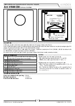
DESCRIPTION
4000 Series vandal resistant camera module (Brushed 2.5mm 12 gauge stainless steel fascia).
The Art. VR4KCM includes a colour CCD high quality day/night wide angle camera. The wide camera has a horizontal viewing angle of 170
degrees. The infrared illumination LEDs are mounted around the camera.
The Art. VR4KCM can be used in video door entry systems: traditional (combined with Art. VR4KAM), VX2200 (combined with
Art. VR4KAM2W) or Videokit (combined with Art. VR4KAMK).
The camera can be set for composite video signal (coax cable) or for balanced video (twisted pair cable).
SIGNALS (TERMINALS)
SL
Active low input to enable the camera lightning (the
jumper JP2 must be moved in “SL“ position)
SB
Heater ground input
V2
Balanced video signal sync-
V1
Balanced video signal sync+
V
Coax video signal
—
Ground input
SB
Heater plus input 12V
+20 20Vdc power supply input
+12 12Vdc power supply input
SETTING
The JP1 jumper sets the video signal mode:
• NC = Balanced video signal (terminals “V1” and “V2”);
• COAX = Coax video signal (terminals “V” and “—”);
The JP2 jumper sets the camera switching on mode:
• ON = The camera switches on if supplied on 12 & — or
+20 & — power supply inputs;
• SL = The camera switches on when a 0V is applied to the SL
terminal (a permanent 12 or 20Vdc is required on 12
& — or +20 & —);
TECHNICAL SPECIFICATION
Power consumption while operating: 100mA
Working Temperature:
-10 +50°C
Tensione di alimentazione:
12Vdc/24Vdc
Art. VR4KCM
Camera module

