66550060-EN - V1.0 - 05/02/14
24
IPVK - IPVKC Series IP videokit
IPVK-IPVKC - Installation handbook
• Intercommunication with other devices of the system (outdoor stations, videophones, tablet or PC with client installed) user can
be selected through a complete contacts list or through “favorites” (communication with outdoor stations is audio/video and it’s
possible to activate the relays);
• It is possible to activate the relays of the outdoor stations through a menu option;
• “Weather forecast” function through google weather service (an internet connection to the network is required);
• Melody and desktop can be customized by loading audio files and pi tures.
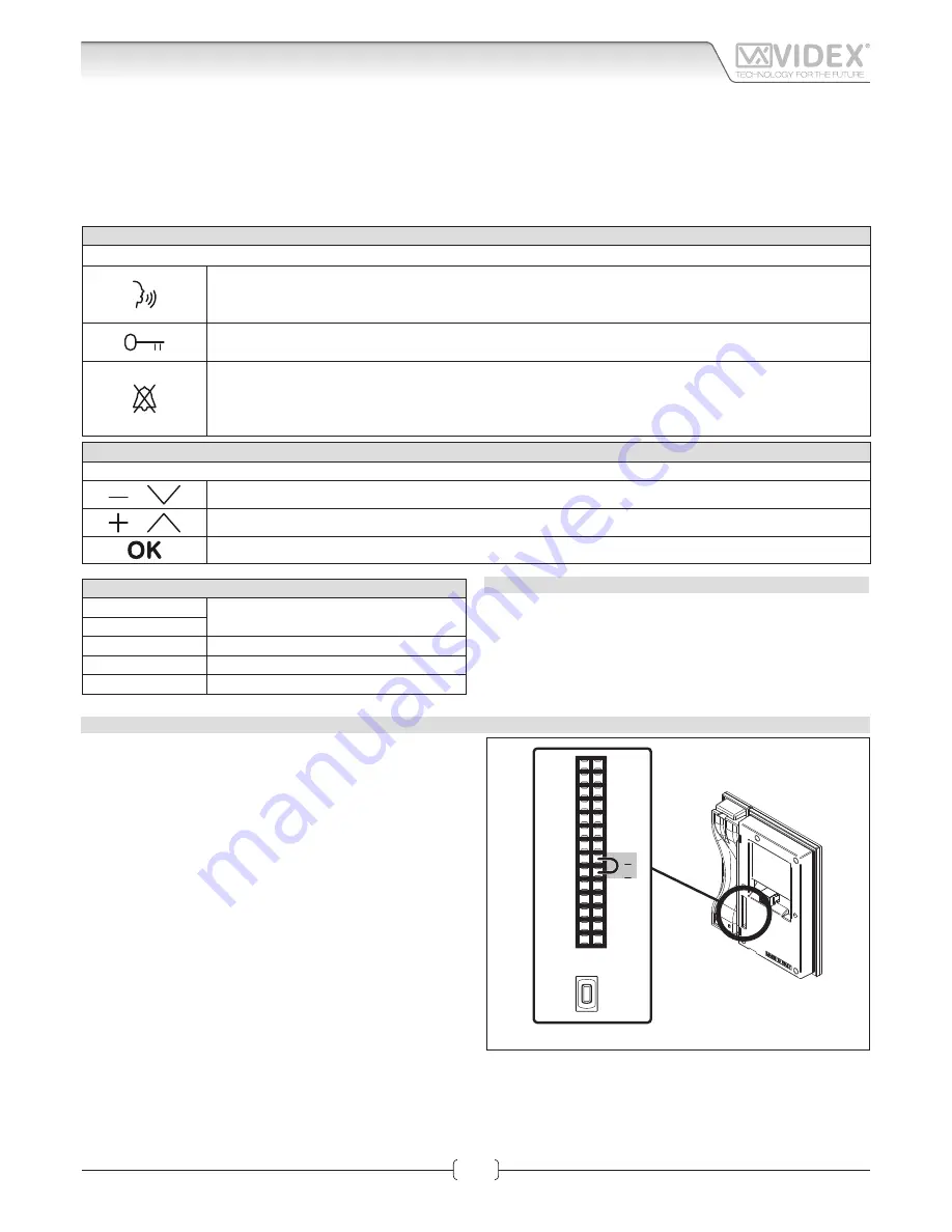
BUTTONS OPERATION IN STANDBY MODE
With the video intercom in stand-by and the monitor swit
ched off
, press any button to switch on.
RAPID CALL BUTTON
By pressing this button you access directly into the “rapid call” submenu. If the list includes one contact only
the call starts directly.
LOCKS
By pressing this button you access directly into the “locks” menu (See LOCKS paragraph in Graphic Interface section).
PRIVACY FUNCTION
By pressing this button you enable the privacy service (the relevant LED switches on) and the videointercom
receives incoming calls but doesn’t switch on the audio or the video connection.
The service is disabled by the privacy time expiring or by pressing the same button again.
MENU NAVIGATION BUTTON
If the videointercom is in stand-by but the monitor is swit
ched off
, first p ess any button to switch on the display.
or
With the videointercom in stand by and switched on it selects the previous menu icon
or
With the videointercom in stand by and switched on it selects the next menu icon
With the videointercom in stand by and switched on it enters in the currently selected menu icon
TERMINALS
L
Not used
H
LAN
10/100Mb Ethernet Interface RJ45 plug
+12Vdc
12Vdc - 500mA Power Supply Input
0Vdc
Ground
TECHNICAL SPECIFICATION
• Power supply voltage:
12Vdc
• Power consumption:
500mA max
• Working temperature:
-10° +50° C
IP VIDEOINTERCOM RESTORE TO FACTORY PRESET
To restore the settings to the factory preset proceed as follows:
1. Power down the video intercom (disconnect the power sup-
ply connector or in case of POE switch/router disconnect the
Ethernet cable);
2. On the rear side of the video intercom, on the 28 way con-
nector, put in short the two terminals as shown in Fig. 3;
3. Power on the video intercom and wait for the boot;
4. Remove the link when the video intercom emits an acoustic signal;
5. Once the boot is complete the video intercom is ready to work;
The video intercom settings are restored to the following:
Network Parameters
IP Address:
192.168.1.4
Net Mask:
255.255.255.0
Gateway:
192.168.1.1
DNS Server:
8.8.8.8
Login Credentials
Username:
admin
Password:
admin
Advanced Setup Password
Password:
0000
14
13
12
11
10
9
8
7
6
5
4
3
2
1
28
27
26
25
24
23
22
21
20
19
18
17
16
15
RESET
BUTTON
Fig. 3
Art. KRV98-KRV96
3.5" IP Videointercom
Connection


