7
3 INSTALLATION
3.1 What is in the box?
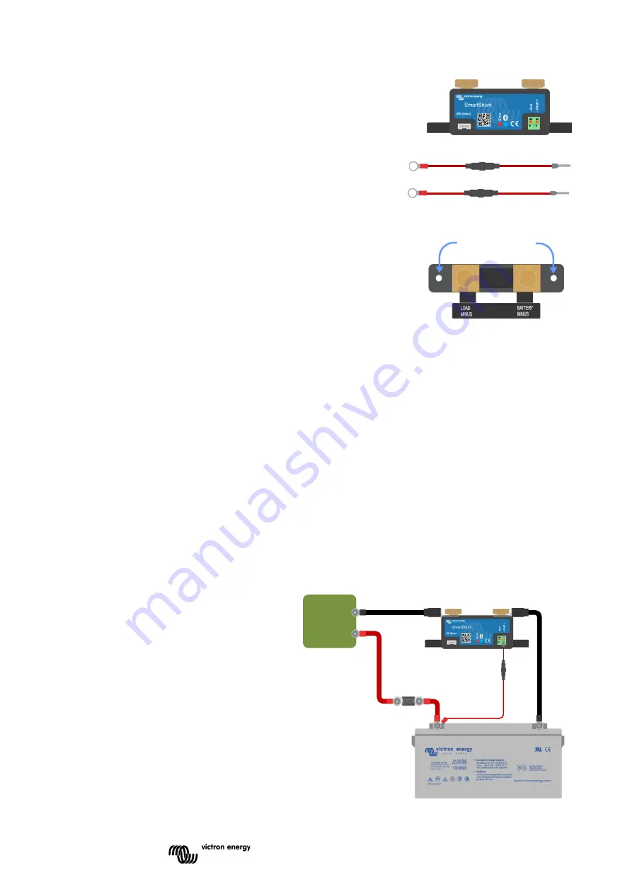
In the box you will find the following parts:
•
SmartShunt 500A, 1000A or 2000A.
•
Two red cables, both with fuse.
3.2 Mounting
The SmartShunt has two 5.5 mm holes for mounting purposes located in the
base of the SmartShunt. The holes can be used to screw or bolt the
SmartShunt onto a hard surface (screws are not included).
The SmartShunt is rated IP21. This means that the SmartShunt is not
waterproof and has to be mounted in a dry location.
3.3 Basic electrical connections
The SmartShunt has 3 essential connections and one optional connection. This chapter describes how to
connect these.
3.3.1
Battery minus connection
Connect the negative of the battery to the M10 bolt on the “BATTERY MINUS” side of the SmartShunt.
3.3.2
Load minus connection
Connect the negative of the electrical system to the M10 bolt on the “LOAD MINUS” side of SmartShunt. Make
sure that the negative of all DC loads and charge sources connect “after” the SmartShunt.
3.3.3
Vbatt+ connection
Connect the M8 terminal of the red cable with fuse to the positive terminal of the battery
Connect the ferrule pin of the red cable with fuse to the SmartShunt by pushing the pin into to the “Vbatt+”
terminal.
As soon as the fuse is placed in the cable, the
SmartShunt Bluetooth will start blinking. The
SmartShunt is now active. The next step is to set
up with the VictronConnect App. This is explained
in chapter 4: “Commissioning”.
In case the Aux port is going to be used for
monitoring a second battery, midpoint or
temperature, see one of the next 3 paragraphs on
how to do this and then go to chapter 4:
“Commissioning”.
mounting holes
DC
Loads
Содержание SmartShunt 1000A
Страница 1: ...EN Manual SmartShunt 500A 1000A 2000A...


