background image

5

Onboard App Introduction

Cortex Onboard is a free Android and Apple 

iOS app that connects your phone or tablet 

to the WiFi of the M1.
Use the Cortex Onboard App to configure, 

manage and display M1 data. The 

Configuration Menu is used for initial 

configuration, AIS programming, network 

settings, firmware updates and input / 

output sensor setup.
Once the M1 is configured, the Cortex 

Onboard App provides access to all M1 

status and smartAIS display screens in a 

similar layout to a Cortex handset. 

See 

To update M1 firmware

 (pg24).

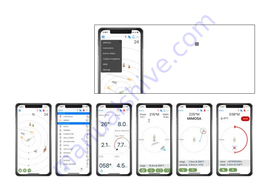
  Cortex Onboard App Main Menu options

  Select the Main Menu icon (   )


Plotter


Plotter view of AIS targets


Directory


AIS targets and manual DSC contacts


Instruments


GPS, integrated sensors and NMEA data


Anchor watch 


Monitor the vessel at anchor


Collision avoidance

  Manage a potential collision scenario


MOB


Man Overboard monitoring


Settings


Configure and manage the M1 

Collision avoidance

Anchor watch

Instruments

MOB

Directory

Plotter

Содержание Cortex M1

Страница 1: ...1 M1 INSTALLATION GUIDE M1 HUB USA CANADA M1 HUB REST OF WORLD ...

Страница 2: ...ming introduction 20 To program an MMSI with the Onboard App 20 To program an MMSI with a handset 21 To confirm AIS operation 21 Monitoring and control 22 Cortex Monitor App introduction 22 To program GPIO sensors with the Cortex Onboard App 23 To program GPIO sensors with a handset 23 Heading Sensor 24 To update M1 firmware 24 M1 Wiring color codes 25 NMEA PGNs and Monitoring Instruments 26 GPIO ...

Страница 3: ...hese updates often add new features To be notified when an update is available please register your Cortex at www vespermarine com register Register Your Cortex Visit www vespermarine com faqs for answers to frequently asked questions technical support downloads local dealer contacts and more Questions and FAQs The M1 hub also features an integrated GNSS receiver supporting GPS GLONASS BeiDou Gali...

Страница 4: ...e Mobile device running the Cortex Onboard App or a Cortex H1 or H1P handset for configuring Optional accessories Cortex H1 or H1P handset s External speaker External cellular antenna NMEA 2000 cable NMEA 2000 T connector NMEA 2000 network extension cable External sensors for Monitoring and Control External cellular antenna optional M1 hub GPS antenna included External WiFi antenna included Cortex...

Страница 5: ...ex Onboard App provides access to all M1 status and smartAIS display screens in a similar layout to a Cortex handset See To update M1 firmware pg24 Cortex Onboard App Main Menu options Select the Main Menu icon Plotter Plotter view of AIS targets Directory AIS targets and manual DSC contacts Instruments GPS integrated sensors and NMEA data Anchor watch Monitor the vessel at anchor Collision avoida...

Страница 6: ...tenna included WiFi data AIS VHF Antenna External Speaker Cortex Handsets WiFi Antenna included Cellular Antenna NMEA 0183 Remote monitoring Input and Output examples Power 12 24V High water Hatch sensor Lighting Motion sensor Bilge pump Chart plotter The Cortex network ...

Страница 7: ...icon indicates VHF AIS and DSC as these functions are all connected to the same AIS VHF antenna Power ON is indicated with white light See M1 LED icon troubleshooting pg36 1 WiFi Antenna port 2 GPS Antenna port 3 Cellular Antenna port 7 NMEA 2000 port 8 Input Output port NMEA 0183 and GPIO sensors 2 4 DC Power Supply 12V or 24V DC 5 Auxiliary VHF port 6 VHF Antenna 1 3 4 5 6 9 Audio port External ...

Страница 8: ... mounting Cables Allow 2 50mm WiFi Antenna Allow 8 200mm Cables Allow 2 50mm Allow at least 2 50mm at each connector row to give sufficient room for cable clearance and connection Allow at least 8 200mm for the external WiFi antenna to be positioned in a vertical position to increase WiFi range For optimal Heading Sensor performance do not mount on or near ferrous materials See Heading Sensor intr...

Страница 9: ...r cable to the M1 Tighten the power cable lock ring clockwise to ensure a secure connection and watertight seal Turn the vessel s batteries and or switch or circuit breaker on to apply power to the M1 Confirm the M1 is powered on with a visual check on the M1 indicator lights M1 wiring diagram Power ve FUSE Negative ve HINT Connect the M1 to a power supply that will remain on even when the vessel ...

Страница 10: ... a minimum of 3m 10ft from any other VHF or HF antennas and not within the beam path of a radar Inadequate separation may damage the Cortex transponder and void your warranty CAUTION Never operate the M1 unless it is connected directly to a suitable VHF antenna HINT The VHF indicator light will display red when a problem is detected with the antenna system ie the VSWR is above the acceptable level...

Страница 11: ...2000 0183 or WiFi The antenna cable is terminated with an SMA connector to facilitate easy routing through holes and openings Do not cut the cable without the correct tools to crimp on a new connector HINT Use the GPS Status screen in the Onboard App or handset to view the satellite signal strengths and determine the best location for mounting the external GPS antenna CAUTION The Vesper Marine GPS...

Страница 12: ...nication such as Iridium Go antennas Consider the distance between the handset and M1 onboard Some objects and materials such as steel aluminum and carbon composites may provide interference to degrade the WiFi signal strength External Wifi Antenna Configuration Cortex Onboard App Menu Settings Device Settings Networks WiFi Use external antenna select on off Cortex handset Main Menu Touch on the w...

Страница 13: ... sent and received by the gateway pg26 Example Case 1 Sailing and navigation apps cannot talk directly to an NMEA 2000 network as the apps use the 0183 protocol We need to translate data from NMEA 2000 to 0183 Gateway The M1 receives NMEA 2000 PGNs and automatically converts these to 0183 sentences and sends to devices running the sailing and navigation apps via WiFi Example Case 2 A vessel has an...

Страница 14: ...el s NMEA 2000 network Modifying the Instance or System Identification can be done via the Cortex Onboard App or from the H1 handset Cortex Onboard App Menu Settings Device Settings Networks NMEA 2000 Device Instance 0 255 select to enter value System Instance 0 255 select to enter value Cortex handset Main Menu Touch on the wrench icon to open the Configuration Menu Networks N2000 NMEA 2000 Devic...

Страница 15: ...uch on the wrench icon to open the Configuration Menu Networks 0183 NMEA 0183 Baud In Baud out HINT AIS output requires a minimum of 38400 Baud rate Note When connecting the M1 to NMEA 0183 devices connect 0183 Common Black to the vessel s negative bus This is to ensure a satisfactory grounding as the NMEA 0183 network of the M1 is isolated POWER VE POWER VE FUSE ORANGE WHITE DARK GREEN YELLOW NME...

Страница 16: ...easy routing through holes and openings Do not cut the cable without the correct tools to crimp on a new connector Do not extend the antenna cable beyond the supplied length of 5M 16 HINT A solid orange light on the LED indicator panel indicates an attempt to connect to a cell tower green indicates connection See LED icon troubleshooting pg36 for further information External Antenna Configuration ...

Страница 17: ...er Marine External Speaker Part Number 111210 is purpose designed for the marine environment Featuring IP66 ingress protection this speaker is suitable for installing almost anywhere on board 3 70 Watt Speaker Frequency response of 80Hz 18kHz 4 ohm impedance IP66 water resistant for marine applications UV resistant polymer housing Polypropylene cone Heavy duty molded ABS plastic basket and grill P...

Страница 18: ...M1 2 Select WiFi in the settings of the device From the list of available WiFi identify and select the M1 WiFi SSID Note The WiFi SSID is identified by the M1 serial number eg CORTEX 95211616 Key the WiFi password found on the label supplied with the M1 Alternatively scan the QR code of the M1 found on the WiFi label to be automatically connected Join and save to connect Close the WiFi setting on ...

Страница 19: ...Trying to connect for a long period it has not made a WiFi connection to the M1 Confirm the M1 is ON Check the WiFi signal strength on the mobile device or in the Status Bar of the handset Check the M1 WiFi External Antenna is attached Consider the distance between the device and M1 on board Some objects and materials may provide interference to degrade the WiFi signal strength See Connecting to a...

Страница 20: ...SI with the Onboard App Before an M1 can transmit your position over AIS you must configure your vessel details and enter a valid MMSI number You can configure your MMSI using the Cortex Onboard App or a Cortex handset Your MMSI may have been entered by your dealer You must have an assigned MMSI for your vessel If you do not have an assigned MMSI contact the relevant authority in your country Once...

Страница 21: ...a handset Main Menu Select the wrench icon to open the Configuration Menu Vessel Dimensions Length Enter length overall Beam Enter beam overall GPS from stern Enter measurement GPS from starboard Enter measurement To program an MMSI with a handset Green light indicates AIS data transmission To confirm AIS operation Onboard App or handset Status Bar pictured VHF LED indicator panel Main Menu Select...

Страница 22: ... built in cellular modem and the Cortex Monitor App on your phone Once the M1 is installed and operating data from the M1 s integrated sensors from external sensors wired into the GPIO port and data from an NMEA bus will be displayed and controlled on the Cortex Monitor App M1 integrated sensors GPS position System voltage Vessel heading refer Heading Sensor Calibration pg24 Barometric pressure M1...

Страница 23: ...re up to 5 general purpose sensors 3 x input 2 x input output 1 Turn Cortex M1 and handset ON Switch the vessels batteries ON to power the M1 2 Connect the handset to the M1 via WiFi See Connecting to an M1 section 3 Select the handset Main Menu and program as follows Main Menu Select the wrench icon to open the Configuration Menu Sensors GPIO Sensor control name Sensor control type select from li...

Страница 24: ...ntated AIS icon of your vessel on another vessels AIS system The heading sensor also determines the direction to the bow for Anchor Watch Note The heading sensor is not available for use by the Plotter or Instruments views or output on the NMEA 2000 bus The heading sensor requires calibration that is performed from the Onboard App or a handset Firmware updates for the M1 hub and H1 H1P handsets ar...

Страница 25: ...LIGHT GREEN INPUT OUTPUT 2 BROWN INPUT OUTPUT 1 GRAY INPUT 3 VIOLET INPUT 2 BLUE INPUT 1 RED PULLUP VOLTAGE NMEA TX A NMEA TX B NMEA RX A NMEA RX B AUDIO VE AUDIO VE Reserved Do not connect Reserved Do not connect BLACK RED POWER VE POWER VE BLACK NMEA 0183 COMMON and GPIO GROUND ...

Страница 26: ...129809 AIS Class B CS Static Part A 129810 AIS Class B CS Static Part B 130306 Wind data Sent PGNs PGN Description 0183 Translation 127250 Vessel Heading HDG 128259 Speed water referenced VHW 128267 Water depth DPT 128275 Distance log VLW 129283 Cross track error XTE 129284 Navigation data BOD APB RMB 129285 Navigation route waypoint info WPL RMB 129810 Wind data MDW MWV 129284 Actual Pressure XDR...

Страница 27: ...iring Lighting remote control GPIO sensor configuration example Sensor control name Anchor light Sensor control type On Off switch Note Lighting on off remote control is one example of what an output relay may switch and control Note An external Pullup voltage connection is recommended when connecting GPIO sensors to the M1 When a sensor does not provide more than 2V the Pullup provides an appropr...

Страница 28: ...ion sensor Sensor control name Cockpit Motion 1 Sensor control type Security sensor Default input high Pullup enabled Active when high Yes normally closed GPIO sensor configuration example Note An external Pullup voltage connection is recommended when connecting GPIO sensors to the M1 When a sensor does not provide more than 2V the Pullup provides an appropriate high level reference for the M1 s i...

Страница 29: ...er sensor GPIO sensor configuration example Sensor control name Bilge high water Sensor control type High water sensor Default input high Pullup enabled Active when high No normally open Note An external Pullup voltage connection is recommended when connecting GPIO sensors to the M1 When a sensor does not provide more than 2V the Pullup provides an appropriate high level reference for the M1 s inp...

Страница 30: ...arm Bilge pump Three way switch manual on off auto on INPUT OUTPUT 2 INPUT OUTPUT 1 GPIO sensor wiring Bilge pump activation sensor GPIO sensor configuration example Note A Pullup connection is not required in this example as it is driven high Sensor control name Engine room bilge Sensor control type Bilge pump Default input high Pullup disabled Active when high Yes normally closed ...

Страница 31: ...ensor wiring Hatch door open sensor GPIO sensor configuration example Sensor control name Forward Hatch 1 Sensor control type Security sensor Default input high Pullup enabled Active when high No normally open Note An external Pullup voltage connection is recommended when connecting GPIO sensors to the M1 When a sensor does not provide more than 2V the Pullup provides an appropriate high level ref...

Страница 32: ...eat sensor GPIO sensor configuration example Sensor control name Engine room smoke Sensor control type Smoke sensor Default input high Pullup enabled Active when high No normally open Note An external Pullup voltage connection is recommended when connecting GPIO sensors to the M1 When a sensor does not provide more than 2V the Pullup provides an appropriate high level reference for the M1 s input ...

Страница 33: ...ENERAL HUB SIZE 168 x 168 x 58 7mm 6 5 8 x 6 5 8 x 2 5 16 POWER SUPPLY 9 33V 12V 6A max 500mA nom WEIGHT 770g 1 7lb ENVIRONMENTAL Waterproof IPx7 OPERATING TEMPERATURE 25 C to 55 C 13 F to 131 F SUPPORTED PROTOCOLS AIS Class B SOTDMA VHF Voice Class D DSC ATIS user configurable EU region NOAA Weather US region TRANSMITTER FREQUENCY ERROR Less than 300Hz ANT CONNECTOR SO239 SPLITTER Max input power...

Страница 34: ... 1mm 1 Back Front 20 8mm 13 16 168mm 6 5 8 147 5mm 5 13 16 147 5mm 5 13 16 58 7mm 168mm 6 5 8 Dimensions 58 7mm 2 5 16 58 7mm 2 5 16 164 8mm 6 1 2 71 8mm 2 13 16 21 4mm 75 6mm 3 73 3mm 2 7 8 18mm 11 16 25 1mm Back 20 8mm 13 16 168mm 6 5 8 147 5mm 5 13 16 147 5mm 5 13 16 168mm 6 5 8 58 7mm 2 5 16 58 7mm 2 5 16 164 8mm 6 1 2 71 8mm 2 13 16 21 4mm 7 8 75 6mm 3 73 3mm 2 7 8 18mm 11 16 25 1mm 1 Back Fr...

Страница 35: ...7 8 Ø60mm 2 3 8 Ø42mm 1 5 8 19 5mm 3 4 Ø2mm 18 5mm 3 4 15mm 5 8 7mm 1 4 21 5mm 7 8 Ø60mm 2 3 8 Ø42mm 1 5 8 0 5 1 Scale Bottom Diameter 21 5mm 7 8 Ø60mm 2 3 8 Ø42mm 1 5 8 19 5mm 3 4 Ø2mm 1 16 26mm 1 59mm 2 5 16 53mm 2 1 8 22mm 7 8 4mm 5 32 20mm 13 16 18 5mm 3 4 15mm 5 8 7mm 1 4 21 5mm 7 8 Ø60mm 2 3 8 Ø42mm 1 5 8 0 5 1 Scale Ø22mm 7 8 Ø63mm 2 1 2 Ø52mm 2 1 16 Ø 4 2 m m 1 5 8 Ø 3 2 m m 1 1 4 4mm 5 32...

Страница 36: ...smit it requires 1 minute to initialize MMSI not programmed A valid MMSI must be programmed before you may transmit your position see To program your MMSI number section Stealth mode Stealth mode is on Last position report not sent This may happen from time to time in very busy areas with lots of AIS traffic This is normal behaviour for a Class B AIS device VHF Orange Flashing AUX VHF is transmitt...

Страница 37: ...A bus connected and exchanging information with the M1 NMEA 2000 Red Solid NMEA 2000 bus error detected Check the integrity of the NMEA network cable and terminating resistors FUNCTION COLOR STATE DESCRIPTION Cloud Orange Solid Attempting to connect or connected to a cellular network Cloud Orange Flashing Flashes when attempting to connect to the Vesper Cloud Cloud Green Solid Connected to the Ves...

Страница 38: ...lies with RSS 310 of Industry Canada Operation is subject to the condition that this device does not cause harmful interference To satisfy RF exposure requirements for mobile transmitting devices a separation distance of 2 metre or more should be maintained between the antenna of this device and persons during device operation To ensure compliance operations at closer than this distance is not rec...

Страница 39: ...mer shall be responsible for any transportation costs This warranty does not cover failures due to abuse misuse accident improper installation unauthorized alterations or repairs shipping damage wear and tear or corrosion This warranty does not cover defects or damage caused if the product s external housing has been opened the serial number or other labels have been removed or altered or the spec...

Страница 40: ...ortions of this product may use software licensed under open source license agreements Source code for the applicable software is available upon request from Vesper Marine Ltd Member of CortexM10709 500 100310 01 Vesper Marine declares that this product is in compliance with Directive 2014 53 EU The full text of the EU Declaration of Conformity is available at the following internet address www ve...

Отзывы: