EN
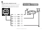
GPIO sensor wiring - Bilge pump activation sensor
32
GPIO sensor wiring - Bilge pump activation sensor
A Pullup connection is not required in this example as it is driven high.
LIGHT GREEN
BROWN
GRAY
VIOLET
BLUE
BLACK
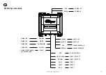
INPUT 3
INPUT 2
INPUT 1
GPIO GND
RED
PULLUP VOLTAGE
(not requied in this example)
INPUT/OUTPUT 5
INPUT/OUTPUT 4
+ve 12/24V
-ve
+
Float switch
Warning light
or alarm
Bilge pump
Three way switch
manual on / off / auto on
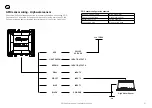
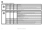
GPIO sensor configuration example
Sensor / control name
Engine room bilge
Sensor / control type
Bilge pump
Default input high
Pullup disabled
Active when high
Yes, normally closed


