Appendix 4 Engineering Design Diagram 101
NetSure 801 CA7 Power Supply System (New Skelecton) User Manual
93.1
437.0
2000.0
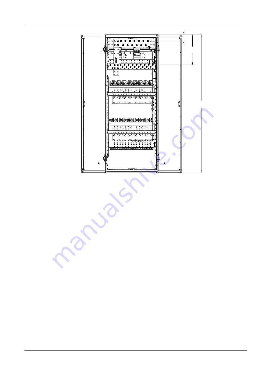
Figure 10 PD48/1600DF-7-Y4 engineering design diagram (rear view, unit: mm)
Страница 1: ...sers may contact the nearest Vertiv local sales office or service center Copyright 2018 by Vertiv Tech Co Ltd All rights reserved The contents in this document are subject to change without notice Ver...
Страница 2: ...safety regulations must be observed during the installation of AC power supply equipment The people who do the AC standard installation must be licensed to operate high voltage and AC power During ope...
Страница 3: ...operations on a day with thunderstorms about In thunderstorms strong electromagnetic field will be generated in the air Therefore the equipment should be solidly earthed in time to avoid damage by li...
Страница 4: ...de the metal objects and circuit board thus causing damage to the equipment and short circuit of the circuit board For safety reasons before working on the battery pay attention to the following point...
Страница 5: ...serting single boards to prevent the contact pins on the motherboard to be twisted Insert the boards along the slots to avoid short circuit resulting from the contact of circuit boards Never touch the...
Страница 6: ......
Страница 7: ...eck 22 2 3 2 Tools And Materials Preparation 22 2 4 Unpacking Inspection 24 Chapter 3 Installation 26 3 1 Installing Cabinet 26 3 1 1 Installation On The Floor 26 3 1 2 Installation On Supporting Rack...
Страница 8: ...4 3 2 Setting Basic Parameters For Controller 53 4 4 Checking Alarm And Operation Status 56 4 4 1 Testing Controller 56 4 4 2 Testing DC Distribution 57 4 4 3 Access Controller Through Web 58 Chapter...
Страница 9: ...Appendix 1 Technical Parameter 82 Appendix 2 Alarm List 87 Appendix 3 Terminologies 91 Appendix 4 Engineering Design Diagram 93 Appendix 5 Spare Part List 108 Appendix 6 Wiring Diagram 109...
Страница 10: ......
Страница 11: ...onents 1 1 Model Information Take NetSure 801 CA7 power supply system for example the model information of the NetSure 801 series power supply system is shown in Figure 1 1 NetSure 801 C A The number...
Страница 12: ...cabinet AC distribution cabinet Rectifier cabinet Controller Rectifier Figure 1 2 Three cabinet system structure The technical parameter of the rectifier cabinet is given in Table 1 1 Table 1 1 Techni...
Страница 13: ...3P 1 32A 1P 3 20A 1P 3 PD380 630AFH 7 Y3 8 route 3 phase input 6 route single phase output Output total capacity does not exceed 630A 160A 3P 6 63A 3P 1 32A 3P 1 32A 1P 3 20A 1P 3 PD380 630AFH 7 YF C...
Страница 14: ...NT2 4 200A NT2 4 100A NT00 8 63A NT00 6 PD48 2500DF 7 Y4 26 routes load output 500A NT3 16 200A NT2 4 100A NT00 2 63A NT00 4 DC output Distribution parameter PD48 1600DF 7 YF Configured according to...
Страница 15: ...reen On Off No input and output Flashing The rectifier is being operated through the host Protection indicator Yellow Off On AC input under overvoltage rectifier PFC output under overvoltage high temp...
Страница 16: ...appearances of the AC distribution cabinets are the same as shown in Figure 1 5 AC mains indicator Failure indicator Power distribution LCD Figure 1 5 Appearance of AC distribution cabinet The interna...
Страница 17: ...view door open Figure 1 6 PD380 400AFH 7 Y2 AC distribution cabinet The internal structure of AC distribution cabinet PD380 630AFH 7 Y3 is shown in Figure 1 7 Class C SPD SPD MCB Buzzer Buzzer contro...
Страница 18: ...es Power Supply System User Manual Earth busbar Neutral busbar Cover plate b Rear view door open Figure 1 7 PD380 630AFH 7 Y3 AC distribution cabinet ATS controller ATS Monitoring board AC sampling bo...
Страница 19: ...ystem User Manual Neutral busbar Earth busbar SPD MCB SPD b Rear view door open Figure 1 8 PD380 630AFA 7 Y4 AC distribution cabinet The structure and configuration of PD380 630AFH 7 YF is determined...
Страница 20: ...binet is available in six models PD48 1600DF 7 Y3 PD48 1600DF 7 Y4 PD48 1600DF 7 YF PD48 2500DF 7 Y3 PD48 2500DF 7 Y4 and PD48 2500DF 7 YF The appearances of the DC distribution cabinets are the same...
Страница 21: ...on cabinet PD48 1600DF 7 Y3 is shown in Figure 1 10 Battery II fuse Battery I fuse Buzzer Buzzer control switch Fault silencer Controller LCD Control board Load fuse a Front view open front door DC po...
Страница 22: ...on cabinet PD48 1600DF 7 Y4 is shown in Figure 1 11 Battery I fuse Buzzer Buzzer control switch Fault silencer Controller LCD Control board Battery II fuse Load fuse a Front view open front door DC po...
Страница 23: ...on cabinet PD48 2500DF 7 Y3 is shown in Figure 1 12 Battery II fuse Load fuse Battery I fuse Buzzer Buzzer control switch Fault silencer Controller LCD Control board a Front view open front door DC po...
Страница 24: ...on cabinet PD48 2500DF 7 Y4 is shown in Figure 1 13 Battery I fuse Buzzer Buzzer control switch Fault silencer Controller LCD Control board Load fuse Battery II fuse a Front view open front door DC po...
Страница 25: ...1600DF 7 YFand PD48 2500DF 7 YF are determined by customer requirement See purchase order for description 1 3 5 Rectifier Cabinet Rectifier cabinets Rack 1000 7 and Rack 2000 7 are shown in Figure 1...
Страница 26: ...ion of the AC cabinet AC cabinet AC DC cabinet Display the busbar voltage total load current battery voltage battery current load fuse status and alarm information DC cabinet AC DC cabinet A6V6FU11 mo...
Страница 27: ...en the fault is removed the buzzer will beep again then place K1 to the fault alarm position the buzzer will stop beeping K2 is buzzer switch when K2 is placed to the buzzer ON position the buzzer bee...
Страница 28: ...ommended 2 Clean the air filter periodically to provide clean air 2 1 2 Layout Requirements Of The Equipment Room Air exhaust and ventilation When the power supply is working the main exothermic part...
Страница 29: ...quipment which should not be less than 2m wide Refer to Figure 2 1 for the above requirements No less than 0 2m of clearance should be kept between the battery and the wall and no less than 0 8m of cl...
Страница 30: ...tribution cabinet is not supposed to be directly connected to the secondary side of a transformer with capacity greater than 1000kVA An extra distribution cabinet should be used between PD380 630AFH 7...
Страница 31: ...le terminal station carrier wave repeating station earth station microwave junction center mobile communication machine station 10 Microwave relay station optical cable relay station small sized earth...
Страница 32: ...No 2 2 Storage Conditions The product should be kept in the packing box prior to use The warehouse ambient temperature should range between 40 C and 70 C and the relative humidity should not be higher...
Страница 33: ...nected between PD380 630AFA AC cabinet and rectifier cabinet or between the PD380 630AFA AC cabinet 04116222 W64AASL06 cable suite power cable of A6V6FU11 monitoring board 4 3m 04116169 W64AASL09 cabl...
Страница 34: ...C power supply Grounding busbar One M16 bolt suggested cable CSA 120mm2 The grounding bar of the room PD380 630AFH 7 Y3 AC distribution cabinet AC input MCB 630A Eight M16 bolts suggested cable CSA 24...
Страница 35: ...n it is unpacked The checking should include 1 The number and serial number of the packing cases according to the system packing case number 2 The correctness of the equipment packing according to the...
Страница 36: ...f the rectifier cabinet b Installation size of the AC DC distribution cabinet Figure 3 1 Installation size of the cabinet base unit mm Step 2 drill reserve holes The expansive pipes delivered along wi...
Страница 37: ...nch The cabinet fixation is illustrated in Figure 3 2 Tap bolt Plain washer Cabinet base Ground Spring washer Expansive pipe Figure 3 2 Fixing cabinet with tap bolt 3 1 2 Installation On Supporting Ra...
Страница 38: ...alled shake the cabinet from different directions No obvious shake should be felt 3 1 3 Parallel Connection Between Cabinets Users need to use connection straps to fix adjacent cabinets at the top as...
Страница 39: ...means of parallel connection copper bars The AC DC integrated distribution cabinet and rectifier cabinet are connected by both cables and copper bars Take parallel connections between a rectifier cabi...
Страница 40: ...t DC cabinet AC cabinet AC cabinet Recommended arrangement of 6000A system using Rack2000 7 rectifier cabinet AC cabinet AC cabinet Rectifier cabinet DC cabinet Rectifier cabinet DC cabinet Rectifier...
Страница 41: ...ternal cabling 2000A When the AC output S series of the ABB MCCB for Vertiv 04110146 optional W74AASL11 cable suite AC input cable of the rectifier cabinet 7m 7m No DC cabinet between AC cabinet and r...
Страница 42: ...t the rear lower or rear upper part of the rectifier cabinet to the earth bar of the AC distribution cabinet see Figure 3 8 to Figure 3 10 Earth terminal Earth terminal Figure 3 8 Earth terminal of th...
Страница 43: ...en Rectifier Cabinet And AC Distribution Cabinet For Rack1000 7 rectifier cabinet choose one 160A MCB inside PD380 400AFH 7 Y2 or PD380 630AFH 7 Y3 or PD380 630AFA 7 Y4 cabinet as AC input switch of t...
Страница 44: ...and Figure 3 12 A Phase A line yellow Phase B line green A amplification Phase C line red Bolt Spring washer Plain washer Figure 3 11 Connection of AC input cables phase line of rectifier cabinet in...
Страница 45: ...distribution switch and connected to the output terminal when the power is to be switched on The AC input is fitted with overcurrent short circuit and lightning protection devices The capacity of the...
Страница 46: ...n the DC distribution cabinet to supply DC power for emergency lighting and then connect this fuse to the DC contactor by means of cable which should be sized for the emergency lighting power Follow t...
Страница 47: ...To fuse in DC distribution cabinet cable 1 To busbar in DC distribution cabinet cable 2 To emergency lighting Emergency lighting contactor Emergency lighting busbar A amplification Emergency lighting...
Страница 48: ...e cables are the same color they should be numbered or identified with insulating tape of different colors at both cable ends 2 Add cable lugs to both ends of the cables 3 Select the DC output branch...
Страница 49: ...e cable to the output terminal of the battery fuse and one end of the positive cable to the positive copper bar of the DC distribution cabinet Add cable lugs to the other end of the positive and negat...
Страница 50: ...ion of parallel cabinets is up to requirements Yes No 20 The cables and cable trenching are level horizontally or vertically Yes No 21 Distances between line cable ties are equal and consistent Yes No...
Страница 51: ...mounting and dismounting it 3 4 2 Installing Controller The controller should be installed using the following procedures 1 Unscrew the screws on the dummy plate as shown in Figure 3 23 Screw Dummy p...
Страница 52: ...d PCB or IC chip ESD wrist strap must be worn to prevent body static from damaging the sensitive components The other end of the ESD wrist strap must be well earthed The Installation of the IB2 extens...
Страница 53: ...IB2 user interface board definition Note 1 J11 and J12 are temperature sensor ports They are not used here 2 J2 is I2 C interface and provides the power See Table 3 3 for the dry contact terminal defi...
Страница 54: ...nected the alarm output cables to the terminals DO1 8 silkscreen on IB2 board Note Alarm relay contact capacity Max 1A 60Vdc and 60W Min 10uA 10Vdc Connect digital quantity input The digital input use...
Страница 55: ...re only 2 rectifier cabinets attach the matching resistance here Figure 3 29 Rectifier cabinet CAN communication cable connection diagram 1 rear view When the controller mounted to the rectifier in th...
Страница 56: ...tion Cable Of Distribution Cabinet Connecting RS485 communication cable The distribution cabinets communicate with controller by RS485 communication cables whose connector is DB9 In the three cabinet...
Страница 57: ...abinets according to Figure 3 34 If the cabinet number is different from Figure 3 34 increase or decrease the parallel cables between cabinets according to Figure 3 34 The connection of RS485 cable sh...
Страница 58: ...3 DC cabinet 1 DC cabinet 2 DC cabinet 3 Monitor 0V 48V 0V 48V 0V 48V A6V6FU11 Monitoring board A2V6FX1 Signal transfer board RS485communication cable RS485communication cable AC cabinet 48V power cab...
Страница 59: ...l output Figure 3 35 Connection of temperature sensor 3 AD592BN is current type temperature sensor Ensure that the sixth position temperature sensor selection position of the DIP switch on the DC dist...
Страница 60: ...ccurs The cause of the malfunction must be found out before resuming the operation 4 2 Power on Inspection before power on The inspection steps as below 1 Check that the earth cables of the cabinets a...
Страница 61: ...V difference from the battery voltage through the controller 3 Use insulated tools and connects the battery cables to the batteries according to the instructions of the battery manufacturer The other...
Страница 62: ...N ON voltage type temperature sensor OFF current type temperature sensor AC distribution cabinet can ignore this item 7 Buad rate OFF ON 9600bps OFF 19200bps AC distribution cabinet if OFF by default...
Страница 63: ...asic Parameters For Controller To put the system into service system setting must be done through the controller battery group number battery nominal capacity charge current limit and other function r...
Страница 64: ...g Description Hall Coefficient 3000 Used for PD48 2500DF 1500 Used for PD48 1600DF Load Measure Ty Hall Set to Hall by default 6 Back to DC Settings DC Distrib 1 DC Distrib n set the Num of Battery of...
Страница 65: ...configured ignore this item and set the TempComp Sensor to Ldu1 Temp1 as shown in Figure 4 9 If no temperature sensor is configured or the temperature compensation function needs to be canceled then s...
Страница 66: ...t the communication between the controller and this unit as well as other units in serial connection with this unit and cause the controller to generate communication failure alarm Real time data will...
Страница 67: ...the battery capacity rectifier quantity and load capacity By that time the mains failure alarm will disappear automatically With the output voltage rising to exceed the undervoltage alarm recovery po...
Страница 68: ...4 16 Figure 4 16 LAN setting Step 1 2 In the interface shown in Figure 4 16 click the LAN Settings button to pop up the interface shown in Figure 4 17 Figure 4 17 LAN setting Step 2 In the above inte...
Страница 69: ...Options window opens In the Internet Options window select the General tab as shown in Figure 4 18 Figure 4 18 Internet options 4 Click on the Settings button The following window opens as shown in Fi...
Страница 70: ...elect the Security tab as shown in Figure 4 20 Figure 4 20 Security tab 6 Click on Trusted sites With Trusted sites selected click Sites The following window opens as shown in Figure 4 21 Uncheck the...
Страница 71: ...ick Close as shown in Figure 4 23 Figure 4 23 Adding trusted sites 2 9 In your browser enter http and the controller s IP address and press ENTER If your site requires secure HTTP and you were furnish...
Страница 72: ...the Web Interface after entering a valid User Name and Password and clicking LOGIN the Homepage window opens as shown in Figure 4 25 Figure 4 25 M831D Homepage 11 Check whether all parameters in Figur...
Страница 73: ...rs for the power distribution cabinet through the controller the display will switch to the original screen if the currently displayed parameters are changed The LCDs of AC distribution cabinet are sh...
Страница 74: ...01 On 02 On AC Distri MCCB 03 On 04 On 06 On 07 On 05 On 06 On Indications of AC input MCCB output MCCB state on off The AC output state will be displayed according to the AC output MCCB number set i...
Страница 75: ...l be displayed according to the temperature circuit number set in the controller 3 routes and their actual value When the number is 0 this screen will not be displayed While setting the temperature me...
Страница 76: ...The monitoring unit has three password levels user level password default 1 engineer level password default 2 and administrator level password default 640275 See Table 5 1 Table 5 1 Password levels an...
Страница 77: ...erial No alarm total number alarm name alarm level and alarm time The alarm generating time determines the sequence it is displayed with the latest alarm displayed first Press or to view all active al...
Страница 78: ...ave the setting value See Table 5 2 for parameters of AC distribution settings Table 5 2 Description of the AC parameter setting Parameter name Setting range Default Description AC input Curr None Hal...
Страница 79: ...g to your requirements Reset Paras Y N N Whether resetting the parameter to the default User PWD The password can be 6 digits long at most If it is shorter than 6 digits end it with space key ComDownL...
Страница 80: ...mat This includes status of the input power modules i e rectifiers converters DC equipment and battery 3 Click on the Rectifier icon to access the following window as shown in Figure 5 12 Figure 5 12...
Страница 81: ...fully loaded at the initial operation stage Power interrupt is not allowed once the priority load is put into operation Therefore new load adding must be a live operation Before adding DC load a good...
Страница 82: ...e corresponding AC input switch to feed AC power to this rectifier 5 Repeat steps 1 to 4 to add all rectifiers 6 Reset parameters for controller Notice Note Connection and disconnection of rectifier s...
Страница 83: ...y standards and local regulations 6 1 2 Maintenance Tools And Equipments The common tools and instruments used in maintenance of power supply system are separately listed in Table 6 1 and Table 6 2 Ta...
Страница 84: ...missible voltage drop of power supply circuit V Psophometrically weighted noise Peak peak value noise Wide frequency noise effective value 48 40 to 57 2mV 200mV 0 to 20Mhz 50mV 3 4kHz to 150kHz 20mV 1...
Страница 85: ...rameter setting can refer to the Device user manual 4 Communication function The communication between each system unit and the controller shall be normal and there shall be no record of frequent comm...
Страница 86: ...Hairbrushes leather bellows etch Remove clean and wash the guard boards of the vent ducts and the fan replace them after they have been dried 11 DC cables The permissible voltage drop determined in c...
Страница 87: ...through the controller The status parameters that can be inquired include mains voltage mains frequency DC output voltage boost charge float charge status charge discharge current total load current...
Страница 88: ...n for rectifier Fan is blocked Remove the object which blocks the fan operation The vent duct is expedite there are some blockages at air intake or air outlet Remove the blockage at air intake and air...
Страница 89: ...others When the system voltage is higher than 56 4V the rectifier with bigger output must be faulty Replace it If all the rectifiers show the same symptom you must turn off the monitoring and rectifie...
Страница 90: ...uninterrupted DC power supply of the power supply system some emergency measures shall be taken to cope with the faults that threaten DC power supply Faults that may occur in the power supply system a...
Страница 91: ...ce the effects to the power supply equipments during the process from starting to transition for generator Disastrous accidents Disastrous accidents refer to communication equipment faults arising fro...
Страница 92: ...alarm and protection AC input overvoltage alram point Default 485 10Vac line voltage configurable through controller hysteresis is 10Vac AC input overvoltage alarm recovery point Default 475 10Vac lin...
Страница 93: ...r overvoltage protection in 5s Temperature derating Temperature below 45 C outputs full power 5 800W Temperature above 45 C outputs power as following At 50 C output power is 5 400W At 65 C output pow...
Страница 94: ...3P 1 32A 3P 1 32A 1P 3 20A 1P 3 PD380 630AFA 7 Y4 8 route 3 phase output 6 route single phase output output total capacity not exceeding 600A 160A 3P 6 63A 3P 1 32A 3P 1 32A 1P 3 20A 1P 3 PD380 630AF...
Страница 95: ...AFA 7 Y4 250 PD380 630AFH 7 YF 270 Table 3 Technical parameters of DC distribution cabinet Parameter Category Parameter Description Environmental Operating temperature 5 C 40 C Storage temperature 40...
Страница 96: ...e The DC side can withstand one time of simulated lightning current of 10kA at 8 20 s safety regulation Compliant with IEC60950 Noise The noise is not more than 50dB A when ambient temperature is 30 C...
Страница 97: ...ing method 1 When there are more than 2 rectifiers if the absolute value of the sum of rectifier output current load current of DC distribution unit and battery current is bigger than the 2 5 X number...
Страница 98: ...tifier AC power fails 40 Rect Temp High Observation None This alarm happens when rectifier has over temperature fault 41 Rect Fault Major Relay 4 This alarm happens when rectifier fails 42 Over Voltag...
Страница 99: ...d of battery test 63 VHi Batt Temp Observation 64 High Batt Temp Observation 65 Low Batt Temp Observation 66 TempSensorFail Observation 67 Large DU Batt Batt Fuse Fail Critical Relay 3 The alarm happe...
Страница 100: ...c Ub UnderV Observation Relay 2 105 M3 Uca Uc UnderV Observation Relay 2 106 Input MCCB Trip Critical Relay 2 107 Output MCCB Trip Critical Relay 2 108 SPD Trip Critical Relay 2 109 Comm Fail Critical...
Страница 101: ...current is set to a value that is a multiple of C10 10 hour discharging rate For example this value is set to 0 01C10 if the battery nominal capacity C10 is 300Ah then 0 01C10 means the constant boos...
Страница 102: ...t performed to the battery Constant test current System performs the discharging test at this current The rectifier is in hot redundancy status Charging current limiting point Maximum charging current...
Страница 103: ...Supply System New Skelecton User Manual Appendix 4 Engineering Design Diagram Engineering design diagram for AC distribution cabinet 800 0 206 2 387 5 2000 0 912 0 1134 8 654 0 880 0 1036 0 Figure 1 P...
Страница 104: ...dix 4 Engineering Design Diagram NetSure 801 CA7 Power Supply System New Skelecton User Manual 240 257 2000 833 663 303 250 100 994 800 Figure 2 PD380 630AFH 7 Y3 engineering design diagram rear view...
Страница 105: ...eering Design Diagram 95 NetSure 801 CA7 Power Supply System New Skelecton User Manual 206 2 387 5 800 0 2000 0 912 0 1134 8 654 0 880 0 1036 0 Figure 3 PD380 400AFH 7 Y2 engineering design diagram fr...
Страница 106: ...dix 4 Engineering Design Diagram NetSure 801 CA7 Power Supply System New Skelecton User Manual 240 257 2000 833 663 303 250 100 994 800 Figure 4 PD380 400AFH 7 Y2 engineering design diagram rear view...
Страница 107: ...PD380 400AFH 7YF and PD380 630AFH 7 YF varies according to practical configuration 800 625 5 584 5 65 230 174 8 107 5 672 2 926 7 2000 920 769 4 305 7 156 156 Figure 5 PD380 630AFA 7 Y4 engineering de...
Страница 108: ...CA7 Power Supply System New Skelecton User Manual Engineering design diagram for DC distribution cabinet 648 5 227 5 270 0 120 6 115 5 99 5 694 0 1088 5 2000 0 40 0 800 0 153 5 40 0 Figure 7 PD48 1600...
Страница 109: ...Appendix 4 Engineering Design Diagram 99 NetSure 801 CA7 Power Supply System New Skelecton User Manual 93 1 2000 0 437 0 Figure 8 PD48 1600DF 7 Y3 engineering design diagram rear view unit mm...
Страница 110: ...ineering Design Diagram NetSure 801 CA7 Power Supply System New Skelecton User Manual 652 5 227 5 270 0 120 6 115 5 99 5 694 0 1235 0 2000 0 800 0 Figure 9 PD48 1600DF 7 Y4 engineering design diagram...
Страница 111: ...Appendix 4 Engineering Design Diagram 101 NetSure 801 CA7 Power Supply System New Skelecton User Manual 93 1 437 0 2000 0 Figure 10 PD48 1600DF 7 Y4 engineering design diagram rear view unit mm...
Страница 112: ...Supply System New Skelecton User Manual 652 5 227 5 270 0 120 6 115 5 99 5 694 0 1235 0 2000 0 800 0 Figure 11 PD48 2500DF 7 Y3 engineering design diagram front view unit mm 92 1 2000 0 437 0 Figure 1...
Страница 113: ...Supply System New Skelecton User Manual 652 5 227 5 270 0 120 6 115 5 99 5 694 0 1235 0 2000 0 800 0 Figure 13 PD48 2500DF 7 Y4 engineering design diagram front view unit mm 93 1 437 0 2000 0 Figure 1...
Страница 114: ...User Manual The engineering design diagrams PD48 1600DF 7 YF and PD48 2500DF 7 YF varies according to practical configuration Engineering design diagram for rectifier cabinet 2000 121 7 30 5 67 5 600...
Страница 115: ...Appendix 4 Engineering Design Diagram 105 NetSure 801 CA7 Power Supply System New Skelecton User Manual 309 8 1599 3 1599 3 309 8 Figure 16 Rack2000 7 engineering design diagram rear view unit mm...
Страница 116: ...ix 4 Engineering Design Diagram NetSure 801 CA7 Power Supply System New Skelecton User Manual 2000 121 7 30 5 67 9 600 2000 121 7 67 9 30 5 600 Figure 17 Rack1000 7 engineering design diagram front vi...
Страница 117: ...Appendix 4 Engineering Design Diagram 107 NetSure 801 CA7 Power Supply System New Skelecton User Manual 309 8 1156 6 1156 6 309 8 Figure 18 Rack1000 7 engineering design diagram rear view unit mm...
Страница 118: ...Z A2V6FX1 PD380 630AFH 2 AC DC signal transfer board 03023525 Manufactured Board A2V4FZ A2V4FA1 AC Monitor Transformer Board 02470229 SPD VH40TA385M 385Vac 20Ka 40kA 3 phase 3 1 SPD contact slot mount...
Страница 119: ...04 W04 W04 W04 W04 W04 W04 W04 W06 W06 W06 W06 W06 W06 W06 W06 W06 0V PE W28 PE W28 W01 04116174 W12 W12 W12 48V 48V 0V CAN CAN 1 4 1 6 3 4 3 6 5 4 5 6 7 4 7 6 9 4 9 6 2 4 2 6 4 4 4 6 6 4 6 6 8 4 8 6...
Страница 120: ...JX1 41 W02 W02 W02 W01 HD1 44 43 FU1 47 L1 47 L2 47 L3 47 N L1 L2 L3 N PE SPD12Z PD1 47 Chassis 41 A 41 N 41 B 41 C W02 W02 W02 W04 W04 W04 W04 W04 W04 W04 W04 W04 W04 W01 W01 1 3 5 7 2 4 6 8 3 1 5 2...
Страница 121: ...W06 W06 W06 W04 W06 W04 W06 W04 W06 W04 W06 W04 W06 PE W28 PE W28 W12 W12 0V 48V 0V 48V 0V 48V PE B A C CAN PE CAN Module socket rear view enlarge picture 48V 0V CAN CAN 1 2 1 2 1 2 1 2 1 2 1 2 1 2 1...
Страница 122: ...L3 N PE yellow green red blue Yellow green SPD12Z PD1 47 Chassis L1 L2 L3 N PE SPD12Z PD2 48 Chassis 41 A 41 N 41 B 41 C 42 A 42 N 42 B 42 C 47 L1 47 L2 47 L3 47 N 48 L1 48 L2 48 L3 48 N W02 W02 W01 W...
Страница 123: ...33 J4 2 1 J8 W16 31 J0 1 31 J0 2 31 J1 1 1 31 J1 5 31 J1 2 31 J1 3 31 J1 4 1 J25 33 J5 2 33 J4 3 33 J4 4 33 J4 5 33 J4 6 33 J5 1 8 1 25 3 40 2 39 11 25 2 4 W13 27 1 1 4 J12 1 J14 1 4 J13 1 J2 W14 23 1...
Страница 124: ...3 2 3 1 W3 W2 39 2 W5 39 4 W5 37 LH1 W7 U 38 3 2 38 1 1 V W7 3 3 1 U1 33 J9 2 39 6 1 U2 33 J9 6 1 1 10 FU1 W 11 FU2 35 1XK 2 3 3 2 32 J12 3 1 2XK 36 32 J13 1 1 32 J12 4 W19 32 J13 2 W19 W7 U2 11 1 QS...
Страница 125: ...33 J4 2 1 J8 W16 31 J0 1 31 J0 2 31 J1 1 1 31 J1 5 31 J1 2 31 J1 3 31 J1 4 1 J25 33 J5 2 33 J4 3 33 J4 4 33 J4 5 33 J4 6 33 J5 1 8 1 25 3 40 2 39 11 25 2 4 W13 27 1 1 4 J12 1 J14 1 4 J13 1 J2 W14 23 1...
Страница 126: ...39 4 W5 3 1 W7 U LH1 3 2 38 3 2 37 38 1 V 1 1 U2 33 J9 6 1 U1 33 J9 2 39 6 1 1 FU1 3 3 W FU2 W7 11 10 1XK 35 36 32 J12 3 2XK 32 J13 1 32 J12 4 2 3 W19 32 J13 2 3 2 W19 W7 1 U2 11 1 QS V2 33 J9 7 33 J...
Страница 127: ...R1 board Busbar sampling terminal Shunt sampling port Shunt sampling port 1 32 31 2 1 32 31 2 HDU1U11 65 69 B11 39 11 RS485 cable LCD J4 J3 GND AV1 AV2 AV3 12V 12V GND GND IV1 IV2 IV3 PD2 41 A1V8FA1...
Страница 128: ...X1 U1A 39 8 39 6 39 4 39 2 W5 W5 W5 W5 45 8 45 6 45 4 45 2 W5 W5 W5 W5 43 X1 U2A 43 X1 U2C QF12 64 63 QF11 W13 62 QF10 61 QF9 B11 B12 B14 B12 B11 B14 B11 B12 B14 B12 B11 B14 MCB alarm terminal connec...
Страница 129: ...s circumstance busbar should be used under the MCB choose the busbar pole according to actual configured MCBs Technical requirement U V W W32 W33 W34 output MCB quantity of each entry cable is equal j...
Страница 130: ...BI3 1 2 3 4 5 6 Emergency lighting control 7 8 Connect to the signal transfer board 12 Single output PGND 1 2 3 12 PGND 1 2 3 12 PGND 1 2 3 1 3 J11 J12J13 COM New temperature sensor input New LCD conn...
Страница 131: ...ghting control 7 8 Connect to the signal transfer board 12 Single output PGND 1 2 3 12 PGND 1 2 3 12 PGND 1 2 3 1 3 J11J12J13 COM New temperature sensor input New LCD connecter RJ45 Cell 4 current BI4...
Страница 132: ...S485 48 0 12 12 GND 12 signal lamp signal lamp 1 2 1 2 3 4 5 6 BLVD Battery 1 LVD Battery 2 LVD 1 2 3 4 5 6 Battery 3 voltage Battery 4 voltage Cell 3 current BI3 Cell 3 current BI3 1 2 3 4 5 6 Emerge...
Страница 133: ...4 5 6 BLVD Battery 1 LVD Battery 2 LVD 1 2 3 4 5 6 Battery 3 voltage Battery 4 voltage Cell 3 current BI3 Cell 3 current BI3 1 2 3 4 5 6 Emergency lighting control 7 8 Connect to the signal transfer...