Vertiv™ XTE 802G Generator Room Walk-In-Cabinet Description and Installation Manual
49
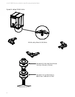
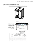
Figure 9-3:
XTE 802G Site Grounding Scheme (Helical Foundation)
(Contractor Installed)
(Contractor Installed)
To the tower ground.
Use one provided #2
stranded cable from the
master ground bar.
Terminate one provided
#2 AWG solid pre-lugged
cable from the master
ground bar to the ground
connection on each WIC
corner plate.
To WIC corner plate
on opposite side.
To WIC corner plate
on opposite side.
Helical
Anchors
Master Ground Bar
(right side)
Front
Grounding
Conductor
Size
Minimum Bending Radius (inches)
(Insulated RHH/RHW)
Solid
(Uninsulated)
Recommended
Required
6 AWG
12
2
1-1/2
4 AWG
12
3
na
2 AWG
12
3
2
1/0 AWG
12
4
na
4/0 AWG
12
4
na
750 kcmil
12
7
na
XTE 802G Site Grounding (Helical Foundation)


